Advertisement
Quick Links
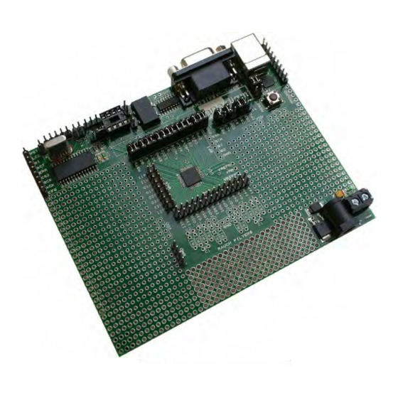
AN231K04-DVLP3 – AnadigmApex Development Board
Figure 1: AnadigmApex Development Board
Disclaimer
Anadigm reserves the right to make any changes without further notice to any products herein. Anadigm makes
no warranty, representation or guarantee regarding the suitability of its products for any particular purpose, nor
does Anadigm assume any liability arising out of the application or use of any product or circuit, and specifically
disclaims any and all liability, including without limitation consequential or incidental damages. "Typical"
parameters can and do vary in different applications. All operating parameters, including "Typical's" must be
validated for each customer application by customer's technical experts. Anadigm does not in this document
convey any license under its patent rights nor the rights of others. Anadigm software and associated products
cannot be used except strictly in accordance with an Anadigm software license. The terms of the appropriate
Anadigm software license shall prevail over the above terms to the extent of any inconsistency.
®
© Anadigm
, Inc. 2013
All Rights Reserved
UM023100-K001h
Page 1 of 16
Advertisement

Related Manuals for Anadigm AnadigmApex

Summary of Contents for Anadigm AnadigmApex
- Page 1 Anadigm assume any liability arising out of the application or use of any product or circuit, and specifically disclaims any and all liability, including without limitation consequential or incidental damages. "Typical"...
- Page 2 AN231K04-DVLP3 – AnadigmApex Development Board 1.0 Overview The AnadigmApex development board is an easy-to-use platform designed to help you get started with implementing and testing your analog designs on the AnadigmApex dpASP silicon devices. While the device on this development platform is an AN231E04 device, you can use this board to implement all ®...
- Page 3 AN231K04-DVLP3 – AnadigmApex Development Board Layout Figures 2 shows the layout of the board allowing easy location of all the components, power connections and jumpers. Figure 2: Top-level layout of the AnadigmApex development board UM023100-K001h Page 3 of 16...
- Page 4 4V and 12V. Anadigm recommends the use of a standard supply regulator or d.c. power supply with a regulated output of either 6 or 9 volt d.c. Note: the board is protected against connection to a supply with the wrong polarity Note: The power supply “jack socket”...
- Page 5 AN231K04-DVLP3 – AnadigmApex Development Board 2) Remove old drivers that have previously been installed. For Windows systems, open the Add or Remove Programs window from the Control Panel. Next, select each CP210x entry and click on Remove. 3) Run the driver executable, CP210x_Drivers.exe, to extract the device drivers included with this release (this application is tested with Windows Only).
- Page 6 AN231K04-DVLP3 – AnadigmApex Development Board Evaluating Multi-chip Designs – Daisy Chaining Figure 3 shows an example of how to chain 2 boards together. More boards can be chained using the instructions shown in this figure. Figure 3: Positions of Jumpers and Default Settings...
- Page 7 AN231K04-DVLP3 – AnadigmApex Development Board Other Features Pins The 3 reference pins on the dpASP device – VMR (+1.5V), VREFP (+2.5V) and VREFN (+0.5V) – have been connected via the p.c.b. tracks to the 3 holes to the right of the dpASP (see figure 2). In addition, VMR is available on the inner ring or inner two rows of pins that are adjacent to the analog I/Os.
- Page 8 ® Anadigm recommends that our customers use their own processor development boards and connect via jumper J5 to Anadigm’s dpASP for fully dynamic control of the dpASP, in preference to re-engineering the digital section of this development board. FLASH Storage In FLASH storage mode, all primary configurations sent to the development board are stored in the FLASH of the PIC.
- Page 9 AN231K04-DVLP3 – AnadigmApex Development Board Jumpers Table 1 shows a complete list of the jumpers on the board and figure 4 shows their positions. Jumper Function Default State Default Condition This jumper allows the MCLRb pin of the PIC to...
- Page 10 AN231K04-DVLP3 – AnadigmApex Development Board Figure 4: Positions of Jumpers and Default Settings Rauch Filters The AN231K04 printed circuit board has an available option for you to use to add Rauch filters, at either the analog input signal path, output signal path or neither. Figure 5 details two suggested Rauch filter circuits.
- Page 11 AN231K04-DVLP3 – AnadigmApex Development Board Figure 5: Suggested Rauch filter circuits For low pass response H(s) = 1/((R1/R2)+ (sC2(R1+R3+(R1*R3/R2)))+ R1R3(2.C1)C2)) R1 = R2 = 2R3 = 2R C1 = 2C2 = 2C Fc = 1/(4π RC(SQRT 2)) Re-arranging these equations for low pass filter R1 = Rin;...
- Page 12 AN231K04-DVLP3 – AnadigmApex Development Board Absolute Maximum Ratings Parameter Symbol Unit Comment DC Power Supply 12.5 DC voltage only jack 3.5mm jack socket Centre pole is positive, outer sleeve is ground DC Power Supply 12.5 DC voltage only Screw terminal “+” post Voltage is relative to “Gnd”...
- Page 13 AN231K04 – the AnadigmApex Development Board UM023100-K001h Page 13 of 16...
- Page 14 AN231K04 – the AnadigmApex Development Board UM023100-K001h Page 14 of 16...
- Page 15 AN231K04-DVLP3 – AnadigmApex Development Board UM023100-K001h Page 15 of 16...
- Page 16 AN231K04 – the AnadigmApex Development Board Notes: For More information Contact http://www.anadigm.com support@anadigm.com UM023100-K001h Page 16 of 16...
Need help?
Do you have a question about the AnadigmApex and is the answer not in the manual?
Questions and answers