
Subscribe to Our Youtube Channel
Related Manuals for Digi DI-5000


Summary of Contents for Digi DI-5000
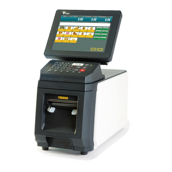
- Page 1 SERVICE MANUAL PC SCALE PRINTER DI-5000 DP-5000 DPS-5000 Edition 2 (Doc. No. SER-SM-072) COPYRIGHT © 2010 TERAOKA WEIGH-SYSTEM PTE LTD...
-
Page 2: Table Of Contents
5.3.5 Weigh & Measure SPEC.......................28 5.3.5.1 SEARCH Function Procedure:................29 5.3.6 Date And Time ........................31 5.3.7 Daylight Saving Time ......................32 5.4 Span Adjustment (Weight Calibration) (For DI-5000 and DPS-5000 Only) ........34 6. SYSTEM SETUP ............................36 6.1 Network Setup ............................36 6.1.1 Scale IP Address........................36 6.1.2 Database IP Address ......................37... - Page 3 9.6 Disassembly of WLAN Kit ........................89 9.7 Disassembly of Thermal Head Unit....................90 9.8 Disassembly of Printer Block......................91 9.9 Disassembly of AD Board (For DI-5000 / DPS-5000 Only)..............92 9.10 Disassembly of Power Supply Unit ....................93 9.11 Disassembly of I/O (Base) Board .....................94 9.12 Disassembly of I/O Interface Board....................94...
- Page 4 13.3.1 Barcode..........................109 13.3.1.1 Item Barcode.....................109 13.3.1.2 Total Item ......................110 13.3.1.3 MultiBarcode .....................111 13.3.2 Communication .........................111 13.3.3 Label ..........................112 13.3.3.1 Advertisement ....................112 13.3.3.2 Currency Symbol ....................112 13.3.3.3 Data Fields ......................112 13.3.3.4 Field Title......................113 13.3.3.5 Ingredient ......................113 13.3.3.6 Label Format.....................113 13.3.3.7 Nutrition......................115 13.3.3.8 Other .........................115 13.3.3.9 Quantity And Symbol ..................116 13.3.3.10 Shop Name .....................116...
- Page 5 13.3.5.29 PLU Search.....................127 13.3.5.30 Preset......................127 13.3.5.31 Product Info.....................128 13.3.5.32 Report ......................128 13.3.5.33 Self Service.....................128 13.3.5.34 Traceability......................129 13.3.5.35 Unit Price Override..................130 13.3.5.36 Unit Price Recalculation..................130 13.4 Module SPEC ..........................131 13.4.1 Password ..........................131 13.4.2 E-label & Hi-Touch ......................131 13.4.3 Queue System & Turn Chime ...................131 13.4.4 Other ..........................131 13.5 Scale SPEC............................133 13.5.1 Scale Price ........................133...
-
Page 6: I) Notice
Notice DIGI ® The material contained in this document is proprietary and for information only and is subject to change without notice. Teraoka Weigh-System Pte Ltd assumes no responsibility for any errors or damages arising from misinterpretation of any procedure. -
Page 7: Ii) Safety Information
ii) Safety Information The operator of the equipment shall comply with the safety and warning indications and procedures outlined in this document. Teraoka Weigh-System Pte Ltd assumes no responsibility or liability for failure to comply with these requirements. • To avoid electric shock, use only the supplied power cords and ensure product is connected to a properly grounded supply. -
Page 8: Iii) Safety Regulations
iii) Safety Regulations Federal Communication Commission Interference Statement This equipment has been tested and found to comply with the limits for a Class B digital device, pursuant to Part 15 of the FCC Rules. These limits are designed to provide reasonable protection against harmful interference in a residential installation. -
Page 9: Iv) Treatment And Recovery Of Weee
RoHS Directives) as well as PCBs and liquids. Only licensed operators meeting WEEE regulations will be able to handle and recover WEEE. Please contact your DIGI office or DIGI distributor when the product has reached the end of its life. They will advise you regarding the product take-back. - Page 10 Items Identification Removal procedure Comments refractory ceramic fibred as described in Commission Directive 97/69/EC of 5 December 1997. Components containing radioactive substances. External electric cables. AC Power Cord. Batteries. 1. Lithium Battery. Refer to Safety Information Warning Disposal Other printed circuit boards greater than 10 square centimeters.
-
Page 11: General
DI-5000_DP-5000_DPS-5000 Service Manual Edition 2 1. GENERAL 1.1 Model Specification Model DI-5000 / DP-5000 / DPS-5000 Dimension 422.6 (L) x 220 (D) x 407.5 (L) Operating System Linux Redhat iMX31 533MHz SD Card 8 GB Memory Mobile 256 ~ 512MB DDRAM 133MHz Display NEC 8.4”... -
Page 12: Overall Dimension (In Mm)
DI-5000_DP-5000_DPS-5000 Service Manual Edition 2 1.3 Overall Dimension (in mm) 422.6 90° rotate (Up and Down) 30° rotate (Turn Left) 30° rotate (Turn Right) -
Page 13: Label Specifications
DI-5000_DP-5000_DPS-5000 Service Manual Edition 2 1.4 Label Specifications φ Outer diameter of rolls: 125mm (Max.) φ Inner diameter of rolls: 40mm Width of label: 80mm (Max.) (max width (liner) is 82mm and max width for printing is 80mm) WIDTH OF LABEL/RECEIPT LABEL TYPE LABEL SIZE PCS/ROLL... -
Page 14: Key Sheet And Display
2.1 Key Sheet Layout And Key Function 2.1.1 Key Sheet Layout DP-5000 DI-5000 / DPS-5000 *Actual legends and symbols may differ depending on local regulations and requirements. 2.1.2 Key Function Refer to the followings for detail explanation for each key on the key panel. - Page 15 DI-5000_DP-5000_DPS-5000 Service Manual Edition 2 TARE Key Set or Clear the tare value. Multiply the number for non-weighting product. MULTIPLY Key Used as ESCAPE key in Programming mode. Calling up PLU in Registration mode. PLU Key Used as ENTER key in programming mode. PRINT Key Printing label or receipt in Registration mode.
-
Page 16: Operator Display Indicator Layout
DI-5000_DP-5000_DPS-5000 Service Manual Edition 2 2.2 Operator Display Indicator Layout Area /Function USAGE Zero Indicator Display when Scale is stable at the zero point Weight Display Display Weight value Price Display Display Unit Price Date & Time Show the current Date and Time. Total Price Display Display Total Price Preset keys... -
Page 17: Software Funtional Structure
DI-5000_DP-5000_DPS-5000 Service Manual Edition 2 3. SOFTWARE FUNTIONAL STRUCTURE MENU Registration Programming Maintenance Report Closing Report Training Mode Web Browser Registration Weighing Mode Programming Preset PrintFMT PLU Related Traceability Setup Product Info Barcode Maintenance Maintenance User Spec Module Spec Scale Spec System Info Maintenance Scale... - Page 18 DI-5000_DP-5000_DPS-5000 Service Manual Edition 2 Hardware Test Input RS-232 Ethernet Drawer Database INIT Backup Restore Load Default Data Database Migration Date And Time Date Time Service Advance Default Data USB Backup RF Bridge Load Default DST Config Restore Data Password Touch Screen Calibration MAC Address Config Firewall TrueType Font Config...
- Page 19 DI-5000_DP-5000_DPS-5000 Service Manual Edition 2 Scale Spec Scale Price Scale Tare Scale Operation Scale Tax System Info Scale Sub CPU Database Boot Flash OS Version Memory Disk Space...
-
Page 20: I/O Ports, Span Switch And W&M Sealing Location
DI-5000_DP-5000_DPS-5000 Service Manual Edition 2 4. I/O PORTS, SPAN SWITCH AND W&M SEALING LOCATION 4.1 I/O Port DP-5000 DI-5000 / DPS-5000 ON/OFF Switch Ethernet RS-232 (COM 1) WLAN RS-232 (COM 2) Bridge (Inside) RS-232 (COM 1) AC Inlet External Platform Connector... -
Page 21: Span Switch (For Di-5000 & Dps-5000)
DI-5000_DP-5000_DPS-5000 Service Manual Edition 2 4.2 Span Switch (For DI-5000 & DPS-5000) 1. Open the Rear 2. Open the Span Cover. switch cover. Push the switch button to Up (Disable) or Down (Enable). -
Page 22: W&M Sealing (For Di-5000 & Dps-5000)
DI-5000_DP-5000_DPS-5000 Service Manual Edition 2 4.3 W&M Sealing (For DI-5000 & DPS-5000) SEALING STICKER SEALING SCREW SEALING THREAD LOADCELL CONNECTOR SEALING FOR LOADCELL CONNECTOR & SPAN SWITCH SEALING FOR LOADCELL CONNECTOR & SPAN SWITCH OPTION BY SEALING STICKER OPTION BY SEALING SCREW AND THREAD... -
Page 23: Initial Setup
DI-5000_DP-5000_DPS-5000 Service Manual Edition 2 5. INITIAL SETUP 5.1 Media Loading 5.2 Switching Printing for Label and Receipt function 1. Press and Hold the button, then press button will switch the printing to [Receipt] function. 2. Press and Hold the button, then press button will switch the printing to [Label] function. -
Page 24: Software Setup
DI-5000_DP-5000_DPS-5000 Service Manual Edition 2 5.3 Software Setup 5.3.1 Default Country SPEC Procedure Picture 1) In Registration mode, select [MENU] [MAINTENANCE] [MAINTENANCE] [SERVICE ADVANCE] (Password: 0953) [DEFAULT DATA]. 2) In DEFAULT DATA mode, select [LOAD FACTORY DEFAULT]. 3) Touch icon to select the country. 4) The machine will auto to compare different of current and default spec. -
Page 25: User Spec
DI-5000_DP-5000_DPS-5000 Service Manual Edition 2 5) Touch [LOAD]. 6) Waiting for the loading default data. 7) After completed, the display will show the successfully message. 5.3.2 User SPEC Procedure Picture 1) In Registration mode, select [MENU] [MAINTENANCE] [USER SPEC]. - Page 26 DI-5000_DP-5000_DPS-5000 Service Manual Edition 2 2) In USER SPEC mode, select the desired SPEC option, e.g. [BARCODE]. Note: Refer to Section 5.5.5.1 on SEARCH function procedures 3) Select the desired SPEC option, e.g. [ITEM BARCODE]. 4) Touch the column and enter new setting or touch the icon to select the new setting.
-
Page 27: Module Spec
DI-5000_DP-5000_DPS-5000 Service Manual Edition 2 5.3.3 Module SPEC Procedure Picture 1) In Registration mode, select [MENU] [MAINTENANCE] [MODULE SPEC]. 2) Enter the Password and press [PLU] key button. Password: 2689 3) In MODULE SPEC mode, select the desired SPEC option, e.g. -
Page 28: Scale Spec
DI-5000_DP-5000_DPS-5000 Service Manual Edition 2 5.3.4 Scale SPEC Procedure Picture 1) In Registration mode, select [MENU] [MAINTENANCE] [SCALE SPEC]. 2) Enter the Password and press [PLU] key button. Password: 3846 3) In SCALE SPEC mode, select the desired SPEC option, e.g. -
Page 29: Weigh & Measure Spec
DI-5000_DP-5000_DPS-5000 Service Manual Edition 2 5) Select [SAVE] button to save the changed setting. 5.3.5 Weigh & Measure SPEC Procedure Picture 1) In Registration mode, select [MENU] [MAINTENANCE] [MAINTENANCE] [SCALE] [W&M SPEC] to go to W&M (Weigh & Measure) SPEC mode. 2) In W&M SPEC mode, select desired SPEC option, e.g. -
Page 30: Search Function Procedure
DI-5000_DP-5000_DPS-5000 Service Manual Edition 2 4) Select [SAVE] button to save the changed setting. 5.3.5.1 SEARCH Function Procedure: Procedure Picture 1) Touch [SEARCH] button. 2) Touch the “Search By” column area. 3) Keyboard screen will pop out. Enter the SPEC no. or key word follow by [ENTER] button. - Page 31 DI-5000_DP-5000_DPS-5000 Service Manual Edition 2 4) Touch [BEGIN] button to start the search process. 5) Message will display on screen indicating the search results as shown. Spec found Spec not found 6) All related SPEC will displayed on the screen.
-
Page 32: Date And Time
DI-5000_DP-5000_DPS-5000 Service Manual Edition 2 5.3.6 Date And Time Procedure Picture 1) In Registration mode, select [MENU] [MAINTENANCE] [MAINTENANCE] [DATE AND TIME] to go to Date And Time menu. 2) At Date mode, use arrow key to select the “Year” and select the date. -
Page 33: Daylight Saving Time
DI-5000_DP-5000_DPS-5000 Service Manual Edition 2 4) Select [SAVE] button to save the change setting. 5.3.7 Daylight Saving Time Procedure Picture 1) In Registration mode, select [MENU] [MAINTENANCE] [MAINTENANCE] [SERVICE ADVANCE] to go to Service Advance mode. 2) Keying the Password and select [ENTER] button. Password: 0953 3) In Service Advance mode, select [DST CONFIG]. - Page 34 DI-5000_DP-5000_DPS-5000 Service Manual Edition 2 4) Keying the “Year”, Start Date”, “End Date” and “Adjust Hours”, then select [ADD] button to adding the setting and select [SAVE] button to save the change setting.
-
Page 35: Span Adjustment (Weight Calibration) (For Di-5000 And Dps-5000 Only)
DI-5000_DP-5000_DPS-5000 Service Manual Edition 2 5.4 Span Adjustment (Weight Calibration) (For DI-5000 and DPS-5000 Only) Note: 1) Ensure the Span Switch is set to [Enable]. 2) Set the W&M Spec setting of [142A005 Loadcell Sensitivity], [142A021 Capacity of Loadcell] and etc. - Page 36 DI-5000_DP-5000_DPS-5000 Service Manual Edition 2 5) Screen shows “Calibrate complete” indicating the process is completed.
-
Page 37: System Setup
DI-5000_DP-5000_DPS-5000 Service Manual Edition 2 6. SYSTEM SETUP 6.1 Network Setup 6.1.1 Scale IP Address Procedure Picture 1) In Registration mode, select [MENU] [MAINTENANCE] [MAINTENANCE] [SCALE IP] to go to SCALE IP mode. 2) Enter setting (Address, Net Mask, Gateway, DNS) according and touch [SAVE] button. -
Page 38: Database Ip Address
DI-5000_DP-5000_DPS-5000 Service Manual Edition 2 6.1.2 Database IP Address Procedure Picture 1) In Registration mode, select [MENU] [MAINTENANCE] [MAINTENANCE] [NETWORK TEST] to go to database network test mode. 2) Keying the database IP Address and touch [PING] button. 3) The display must show [Reply from 127.0.0.1:icmp_seq…] as shown as the picture. -
Page 39: Scale Mac Address
DI-5000_DP-5000_DPS-5000 Service Manual Edition 2 6.1.3 Scale MAC Address Procedure Picture 1) In Registration mode, select [MENU] [MAINTENANCE] [MAINTENANCE] [SERVICE ADVANCE] to go to Service Advance maintenance mode. 2) Keying the Password and select [ENTER] button. Password: 0953 3) In Service Advance mode, touch [MAC ADDRESS]. 4) Editing the MAC Address and then press (Print) key or select [SET] button to save the changed setting. -
Page 40: Wlan (Rf Bridge) Setup
DI-5000_DP-5000_DPS-5000 Service Manual Edition 2 5) MAC Address changing successfully. 6.1.4 WLAN (RF Bridge) Setup Ensure the RF Bridge Kit is plug-in to scale. Procedure Picture 1) In Registration mode, select [MENU] [MAINTENANCE] [MAINTENANCE] [SERVICE ADVANCE] to go to Service Advance maintenance mode. - Page 41 DI-5000_DP-5000_DPS-5000 Service Manual Edition 2 4) Scale will retrieve the current RF Bridge setting. 5) Touch the ESSID column area. 6) Change any ESSID name for Access Point e.g. [RFBRIDGE] and select [ENTER]. 7) Select respective Security and Authentication setting accordingly to the wireless LAN setting.
-
Page 42: Base Station (Bs-02) Setup
DI-5000_DP-5000_DPS-5000 Service Manual Edition 2 6.2 Base Station (BS-02) Setup 6.2.1 Serial Port Configuration Procedure Picture 1) In Registration mode, select [MENU] [MAINTENANCE] [MAINTENANCE] [SERIAL PORT CONFIG]. 2) Select the Com port [/dev/tty/S0] (Com 1) or [/dev/tty/S1] (Com 2), then use key to change the setting. -
Page 43: Language Translation
DI-5000_DP-5000_DPS-5000 Service Manual Edition 2 6.3 Language Translation 1. At PC Windows, open the FTP client program. (E.g. FileZilla Client) 2. Keying the [IP Address], [Username] and [Password], and then click [Quick Connect] button to login DP-5000/DPS-5000 firmware directory folder. 3. - Page 44 DI-5000_DP-5000_DPS-5000 Service Manual Edition 2 5. Right click the [PO] file and select open with [WordPad]. 6. Change the language under the “ “ message of [msgstr] to the other language, and then select [File] [Save] to save the language changed. 7.
-
Page 45: Hardware Test And Maintenance
DI-5000_DP-5000_DPS-5000 Service Manual Edition 2 7. HARDWARE TEST AND MAINTENANCE 7.1 Printer Test 7.1.1 Sensors Status Procedure Picture 1) In Registration mode, select [MENU] [MAINTENANCE] [MAINTENANCE] [PRINTER] [PRINTER TEST] to go to printer test mode. 2) In Printer Test menu, select [STATUS] will show the status of Printer. -
Page 46: Sensor Calibration
DI-5000_DP-5000_DPS-5000 Service Manual Edition 2 5) Close back the printer and touch [FEED] button, and check the [Under Printing] and [Printer Busy] check box will appear a tick mark short a while. 6) When the [Thermistor Warning ON] check box appear the tick mark, that mean the Thermal Head over heating 80°C, once the Thermal Head cool down lower then 60°C, the tick mark will disappear. - Page 47 DI-5000_DP-5000_DPS-5000 Service Manual Edition 2 2) In Printer Test menu, select [SENSOR] and touch [Read All Value] to read the status of Printer. 3) Select [Lite Calibration] to calibrate the gap sensor. A reading of Minimum, Maximum and Threshold will appear. Note: A Threshold value is total of minimum + maximum then divided by 2.
- Page 48 DI-5000_DP-5000_DPS-5000 Service Manual Edition 2 6) Remove the paper roll and then select [Calibration] to calibrate the Paper End Sensor. 7) Remove the label from cassette (without any label or receipt paper) and put back to scale. Then select [OK]. 8) A reading of Minimum, Maximum and Threshold will appear.
-
Page 49: Thermal Head Detected
DI-5000_DP-5000_DPS-5000 Service Manual Edition 2 7.1.3 Thermal Head Detected Procedure Picture 1) In Registration mode, select [MENU] [MAINTENANCE] [MAINTENANCE] [PRINTER] [PRINTER TEST] to go to printer test mode. 2) The display will show the Thermal Head type. -
Page 50: Database Maintenance
DI-5000_DP-5000_DPS-5000 Service Manual Edition 2 7.2 Database Maintenance 7.2.1 Database Initialization Procedure Picture 1) In Registration mode, select [MENU] [MAINTENANCE] [MAINTENANCE] [DATABASE] to go to DATABASE mode. 2) In Database menu, select [INIT]. 3) Select the desired any or all database, then touch [START] button to start initialization. -
Page 51: Database Backup
DI-5000_DP-5000_DPS-5000 Service Manual Edition 2 5) Waiting for initialization progress. 6) Initialization database successfully. 7.2.2 Database Backup Procedure Picture 1) In Registration mode, select [MENU] [MAINTENANCE] [MAINTENANCE] [DATABASE] to go to DATABASE mode. 2) In Database menu, select [BACKUP]. - Page 52 DI-5000_DP-5000_DPS-5000 Service Manual Edition 2 3) Select [YES] to confirm backup database. 4) Waiting for backup database in process. 5) Backup database successfully.
-
Page 53: Database Restore
DI-5000_DP-5000_DPS-5000 Service Manual Edition 2 7.2.3 Database Restore This function only can do in between same PC Scale version in front of the 1 and 2 number is same. For Example: If Backup file from machine PC Scale version is 10.15.17-1, then when restore database for source/other machine the PC Scale version should be 10.15.XX-X Procedure Picture... -
Page 54: Load Default Data
DI-5000_DP-5000_DPS-5000 Service Manual Edition 2 5) Restore database successfully. 7.2.4 Load Default Data Procedure Picture 1) In Registration mode, select [MENU] [MAINTENANCE] [MAINTENANCE] [DATABASE] to go to DATABASE mode. 2) In Database menu, select [LOAD DEFAULT DATA]. 3) Select [YES] to confirm loading the default data. -
Page 55: Database Migration
DI-5000_DP-5000_DPS-5000 Service Manual Edition 2 4) Waiting for default data loading in machine. 5) Loading default data successfully. 7.2.5 Database Migration This function only can do in between same PC Scale version in front of the 1 and 2 number is same. For Example: If the file from machine PC Scale version is 10.15.17-1, then when migration data for source/other machine the PC Scale version should be 10.15.XX-X... - Page 56 DI-5000_DP-5000_DPS-5000 Service Manual Edition 2 2) In Database menu, select [DATABASE MIGRATION]. 3) Select [YES] button. 4) Waiting for database migration progress. 5) Migration Database successfully.
-
Page 57: Usb Backup / Restore
DI-5000_DP-5000_DPS-5000 Service Manual Edition 2 7.2.6 USB Backup / Restore Ensure the USB storage device is plug-in to scale USB port. 7.2.6.1 USB Backup Procedure Picture 1) In Registration mode, select [MENU] [MAINTENANCE] [MAINTENANCE] [SERVICE ADVANCE] to go to Service Advance maintenance mode. - Page 58 DI-5000_DP-5000_DPS-5000 Service Manual Edition 2 5) Select the desired data and touch [CONFIRM] button. 6) Select the disk e.g. [/dev/sda1] to backup and [CONFIRM] button. 7) Waiting for Backup progress. 8) Data backup in USB storage device is successfully.
-
Page 59: Usb Restore
DI-5000_DP-5000_DPS-5000 Service Manual Edition 2 7.2.6.2 USB Restore This function only can do in between same PC Scale version in front of the 1 and 2 number is same. For Example: If USB Backup file from machine PC Scale version is 10.15.20-1, then when restore data for source/other machine the PC Scale version should be 10.15.XX-X Procedure Picture... - Page 60 DI-5000_DP-5000_DPS-5000 Service Manual Edition 2 5) Select the disk e.g. [/dev/sda1] to restored and [CONFIRM] button. 6) Select the desired data and touch [CONFIRM] button. 7) Waiting for Restore progress. 8) Data restored from USB storage device is successfully.
-
Page 61: Hardware Test
DI-5000_DP-5000_DPS-5000 Service Manual Edition 2 7.3 Hardware Test 7.3.1 Input Procedure Picture 1) In Registration mode, select [MENU] [MAINTENANCE] [MAINTENANCE] [HARDWARE TEST] to go to Hardware Test menu. 2) At Hardware Test menu, touch [INPUT] then press scale key button, scan barcode or slide the magnetic card. 3) The screen will show the value (Value may different depend on different data input). -
Page 62: Usb
DI-5000_DP-5000_DPS-5000 Service Manual Edition 2 7.3.2 USB Procedure Picture 1) In Registration mode, select [MENU] [MAINTENANCE] [MAINTENANCE] [HARDWARE TEST] to go to Hardware Test menu. 2) At Hardware Test menu, connect USB keyboard/Mouse to scale USB port, then select [USB] and touch [DETECT] button. -
Page 63: Rs232
DI-5000_DP-5000_DPS-5000 Service Manual Edition 2 7.3.3 RS232 Procedure Picture 1) In Registration mode, select [MENU] [MAINTENANCE] [MAINTENANCE] [HARDWARE TEST] to go to Hardware Test menu. 2) At Hardware Test menu, connect RS-232 Device/Loop Back Test Jig to scale RS-232 com port 1 & 2, then select [RS232] and press [TEST] button. -
Page 64: Ethernet
DI-5000_DP-5000_DPS-5000 Service Manual Edition 2 7.3.4 Ethernet Procedure Picture 1) In Registration mode, select [MENU] [MAINTENANCE] [MAINTENANCE] [HARDWARE TEST] to go to Hardware Test menu. 2) At Hardware Test menu, connect Ethernet LAN cable from PC to Scale and select [ETHENET], then touch [DETECT eth0] button. -
Page 65: Touch Screen Calibration
DI-5000_DP-5000_DPS-5000 Service Manual Edition 2 7.4 Touch Screen Calibration Procedure Picture 1) In Registration mode, select [MENU] [MAINTENANCE] [MAINTENANCE] [SERVICE ADVANCE] to go to Service Advance maintenance mode. 2) Keying the Password and select [ENTER] button. Password: 0953 3) In Service mode, touch [TOUCH SCREEN CALIBRATION]. - Page 66 DI-5000_DP-5000_DPS-5000 Service Manual Edition 2 5) Touch [Circle point] at left side bottom corner and touch key button. (Alternatively, press and hold inside the circle for 3 seconds to continue). 6) Touch [Circle point] at right side center area and touch key button.
- Page 67 DI-5000_DP-5000_DPS-5000 Service Manual Edition 2 9) If completed, the screen will display message [Touch Screen Calibration Success].
-
Page 68: System Information
DI-5000_DP-5000_DPS-5000 Service Manual Edition 2 7.5 System Information Procedure Picture 1) In Registration mode, select [MENU] [MAINTENANCE] [SYSTEM INFO]. 2) In System Info mode, select [Scale] will show the information of “Software Version”, “Model Name”, “AD Version” and “Checksum”. 3) Select [Subcpu] will show the firmware version information of “Printer”... - Page 69 DI-5000_DP-5000_DPS-5000 Service Manual Edition 2 5) Select [Database] will show the information of “Table Record Count”. 6) Select [OS Version] will show the information of “Linux Operating System version”. 7) Select [Memory] will show the information of “Total Ram”, “Free Ram”, “Shared Ram”, “Total Swap”...
-
Page 70: Ad Board Write Checksum (For Di-5000 & Dps-5000)
DI-5000_DP-5000_DPS-5000 Service Manual Edition 2 7.6 AD Board Write Checksum (For DI-5000 & DPS-5000) Note: Ensure the Span Switch is set to [Enable] position 1. From the PC monitor display, select START All Program Run..In Open column, type in the “cmd”... - Page 71 DI-5000_DP-5000_DPS-5000 Service Manual Edition 2 4. Keying password [teraoka] (invisible) and press [Enter]. 5. Keying command [cd /opt/pcscale] and press [Enter]. 6. Keying command [./wrtchksum] and press [Enter]. 7. After checksum have been written successfully, “Done” will appear at the command prompt.
-
Page 72: Maintenance
DI-5000_DP-5000_DPS-5000 Service Manual Edition 2 7.7 Maintenance 7.7.1 Thermal Head Cleaning To maintain good quality printouts and long life span for the thermal print head, regular cleaning of the thermal print head is required. Please use the cleaning kit supplied with the product. Instruction 1. -
Page 73: Basic Cleaning
DI-5000_DP-5000_DPS-5000 Service Manual Edition 2 4. After cleaning, push back the printer front cover into the main unit. 5. Turn ON the scale, and depress [FEED] key to feed label. 7.7.2 Basic Cleaning Clean scale surfaces periodically with a soft damp cloth. Do not use alcohol or detergent. 7.7.3 Dismantled Thermal Head Note: Please ensure switch “OFF”... - Page 74 DI-5000_DP-5000_DPS-5000 Service Manual Edition 2 5. Loosen the 4pcs Binding Head screw. 6. Replace a new Thermal Head. 7. Tighten back the 4pcs Binding Head screw. 8. Connecting back the cable of Thermal Head. 9. Slot the gap to catch the axis bar. 10.
-
Page 75: Firmware Upgrading
DI-5000_DP-5000_DPS-5000 Service Manual Edition 2 8. FIRMWARE UPGRADING 8.1 Kernel RS-232 (COM 1) RS-232 downloading cable AC Inlet DP-5000 machine Procedure Picture 1) At PC screen, click [Start] [All Programs] [Accessories] [Communication] [Hyper Terminal]. 2) Keying the any name (e.g. DP-5000) and click [OK]. 3) Select the [COM 1] and click [OK]. - Page 76 DI-5000_DP-5000_DPS-5000 Service Manual Edition 2 4) Change the Port Settings as below, and then click [Apply] follow by [OK]. Bits per second: 115200 Data bits: 8 Parity: None Stop bits: 1 Flow control: None 5) The Hyper Terminal application is ready. 6) Turn “ON”...
- Page 77 DI-5000_DP-5000_DPS-5000 Service Manual Edition 2 9) Change the Protocol to [Xmodem] then click [Browse…] button. 10) Search and open the bootloader file. Example: bootloader_kernel.bin 11) Click [Send] button. 12) Waiting for process sending file until completed. 13) When completed, monitor will show RedBoot>. 14) Keying command [fis write -f 0xa0000000 -b 0x100000 -l 0x1c0000] and press [Enter].
- Page 78 DI-5000_DP-5000_DPS-5000 Service Manual Edition 2 15) When confirmation displayed, keying [y] and press keyboard [Enter]. 16) Waiting for process, once completed, the monitor will show RedBoot> 17) Keying command [cksum -b 0xa0000000 –l 0x1c0000] and press [Enter]. 18) Checksum should be [0xffbc454c]. Note: If cannot get the correctly checksum, please redo the procedure again.
- Page 79 DI-5000_DP-5000_DPS-5000 Service Manual Edition 2 20) Keying the command [load –b 0x00100000 –r –m xmodem] and press keyboard [Enter] button. 21) Select [Transfer] [Send File…] 22) Ensure Protocol still select [Xmodem] again and click [Browse…] button. 23) To search and open the redboot_config.bin file. Example: redboot_config.bin 24) Click [Send] button.
- Page 80 DI-5000_DP-5000_DPS-5000 Service Manual Edition 2 25) Waiting for process sending file until completed. 26) When completed the monitor will show RedBoot>. Keying command [fis write –f 0xa03f0000 –b 0x100000 –l 0x10000] and press keyboard [Enter] button. 27) When confirmation displayed, keying [y] and press keyboard [Enter] button.
- Page 81 DI-5000_DP-5000_DPS-5000 Service Manual Edition 2 30) Checksum should be [0x9307f20e]. Note: If cannot get the correctly checksum, please redo the procedure again. 31) Click [X] to close the program. 32) Click [Yes] to confirm closing the program.
-
Page 82: Pc Scale Application
DI-5000_DP-5000_DPS-5000 Service Manual Edition 2 8.2 PC Scale Application 1. At PC Windows, open the FTP client program. (E.g. FileZilla Client) 2. Enter the scale IP Address; User and Password, then click the [Quickconnect] button. 3. Double click the [ .. ] symbol to go to upper level. 4. -
Page 83: Printer Firmware
DI-5000_DP-5000_DPS-5000 Service Manual Edition 2 8.3 Printer Firmware Procedure Picture 1) In Registration mode, select [MENU] [MAINTENANCE] [MAINTENANCE] [PRINTER] [PRINTER TEST] to go to printer test mode. 2) In Printer Test menu, touch [FIRMWARE]. 3) Touch [READ] to reading the current firmware version. (The Updating Firmware Version will show the new firmware version). - Page 84 DI-5000_DP-5000_DPS-5000 Service Manual Edition 2 5) Touch [YES] to confirm start updating the firmware. 6) Waiting for firmware upgrading process. 7) Firmware updated successfully. 8) Touch [READ] again to confirm the new firmware version is updated.
-
Page 85: Major Part Disassembly
DI-5000_DP-5000_DPS-5000 Service Manual Edition 2 9. MAJOR PART DISASSEMBLY 9.1 Disassembly of Front Cover Front Cover Block 9.2 Disassembly of Main Body Side Cover 45006702800701 Cover AG(PRT L Cover) Screw Type: 101 – Sems B M4x8 45006702800602 Cover AG(PRT R Cover) -
Page 86: Disassembly Of Cpu Board, Inverter Board, Touch Relay Board And Display Lcd
DI-5000_DP-5000_DPS-5000 Service Manual Edition 2 9.3 Disassembly of CPU Board, Inverter Board, Touch Relay Board and Display LCD 45004901801801 Bracket AR(Shield) 45004902300102 Case AA(Inpane Rear TWS) 45006702800901 Cover AI(Inp Base Rea) 45006702801102 Cover AK(Inp IF Cover) Screw Type: 101 – Binding Head M3x8 Screw Type: 101 –... - Page 87 DI-5000_DP-5000_DPS-5000 Service Manual Edition 2 44016790100100 SM5500 Main BD Blk AA (CPU) Item 1 45004990300200 DP5000 I/O Blk AB(Touch Relay) 10AXINV0AH5020 Item 2 DC-AC INV PDA-W00055D50-GP Item 3 Screw Type: 101 – Binding Head M3x6 Display Block Screw Type: 101 – WN1411-KA30-6-TZ (H2)
- Page 88 DI-5000_DP-5000_DPS-5000 Service Manual Edition 2 Item 4 10A1LCD0BC2109 LCD NL8060BC21 45006706900100 Plate AA (Inp Hinge Sup) 45004901801102 Bracket AK (Display-NEC) Screw Type: 101 – Sems B M3x6 102 – Sems A M2.6x6...
-
Page 89: Disassembly Of Keyboard Block
DI-5000_DP-5000_DPS-5000 Service Manual Edition 2 9.4 Disassembly of Keyboard Block Keyboard Block Screw Type: 101 – Binding Head M3x6 9.5 Disassembly of Top Cover Top Cover Block Screw Type: 101 – Sems B M4x8... -
Page 90: Disassembly Of Wlan Kit
DI-5000_DP-5000_DPS-5000 Service Manual Edition 2 9.6 Disassembly of WLAN Kit Screw Type: 101 – Flat Head M3x6 102- Sems B M4x8 0EX00190440030 AP2001G WLAN BRG (2 ETH) Kit Screw Type: 101 – Sems B M4x8... -
Page 91: Disassembly Of Thermal Head Unit
DI-5000_DP-5000_DPS-5000 Service Manual Edition 2 9.7 Disassembly of Thermal Head Unit Screw Type: 101 – Sems B M4x8 45006708800101 Support AA(Head Unit) 45006708300303 Spring AC(Head Backfeed) 12LXTHDTPH81R5 Toshiba 80mm TPH81R5 (81mm 300DPI) 45004902800401 Cover AD(TPH) Thermal Head Block 45004902800300 Cover AC(Sensor) -
Page 92: Disassembly Of Printer Block
DI-5000_DP-5000_DPS-5000 Service Manual Edition 2 9.8 Disassembly of Printer Block 45006702801200 Cover AL (PRN Belt) 45006702800102 Cover AA (PRN Back Wire) Screw Type: 101 – Sems B M3x6 102 - Sems B M4x6 Screw Type: 101 – Binding Head M3x6... -
Page 93: Disassembly Of Ad Board (For Di-5000 / Dps-5000 Only)
DI-5000_DP-5000_DPS-5000 Service Manual Edition 2 9.9 Disassembly of AD Board (For DI-5000 / DPS-5000 Only) Screw Type: 101 – Flat Head M3x6 102- Sems B M3x6 45006702800301 Cover AC (PRN AC) 45004901300100 Axis AA (M3x18) 45004901800700 Bracket AG(Seal) 45004901800600 Bracket AF (Seal Cover) Screw Type: 101 –... -
Page 94: Disassembly Of Power Supply Unit
DI-5000_DP-5000_DPS-5000 Service Manual Edition 2 44016701804700 Bracket BU (AD_BTM_COV) 44016790300400 SM5500 I/F Blk AD (SM_07 AD) Item 5 45004901800401 Bracket AD (AD Top Cover) Screw Type: 101 – Binding Head M3x6 102 – Flat Head M3x6 9.10 Disassembly of Power Supply Unit 12PNPWUTSD2600 SPS TSD260 Screw Type:... -
Page 95: Disassembly Of I/O (Base) Board
DI-5000_DP-5000_DPS-5000 Service Manual Edition 2 9.11 Disassembly of I/O (Base) Board 45004990300300 Elec Assy I/O Blk AC Item 6 Screw Type: 101 – Binding Head M3x6 9.12 Disassembly of I/O Interface Board 102 101 45004901800104 Bracket AA (IO PCB) Screw Type: 101 –... - Page 96 DI-5000_DP-5000_DPS-5000 Service Manual Edition 2 Screw Type: 101 – Sems B M3x6 45004990300400 DP5000 IO Blk AD (RS232,ETH) 45004901800200 Bracket AB (Power PCB) Screw Type: 101 – Binding Head M3x6...
-
Page 97: Hardware Details
DI-5000_DP-5000_DPS-5000 Service Manual Edition 2 10. HARDWARE DETAILS 10.1 Block Diagram 10.1.1 DP-5000... -
Page 98: Di-5000 / Dps-5000
DI-5000_DP-5000_DPS-5000 Service Manual Edition 2 10.1.2 DI-5000 / DPS-5000... -
Page 99: Power Supply Unit
DI-5000_DP-5000_DPS-5000 Service Manual Edition 2 10.2 Power Supply Unit 115V 230V Location Function AC Input Voltage (110V/230V) Connector DC Fan (24V) Connector DC Output Voltage (5V/24V) Connector Jumper Setting 5V or 5.6V (Default) 10.3 CPU Board CN17 CN11 The Component Side... - Page 100 DI-5000_DP-5000_DPS-5000 Service Manual Edition 2 JP2, 3 The Solder Side Location Function For Wireless Bridge (AP2001G) USB Keyboard / Mouse Debug Port Connector Customer Display Connector Ethernet Connector (RJ45) Operator Display Connector VGA Board Base Board – CPU Board Interface Connector CN11 SD Card CN17...
-
Page 101: Option Kits Installation
DI-5000_DP-5000_DPS-5000 Service Manual Edition 2 11. OPTION KITS INSTALLATION 11.1 RF Antenna Installation 1. Pull out to open the rear cover. 2. Remove the 2 pcs Adhesive cover on Antenna. 3. Paste Antenna on the right side cover. 4. Connect and lock end of antenna cable to RF. 5. -
Page 102: Port Pin Configuration And Cable
DI-5000_DP-5000_DPS-5000 Service Manual Edition 2 12. PORT PIN CONFIGURATION AND CABLE 12.1 Ethernet Port Straight cable is for Client / Server connection. Crossover cable is for Hub-to-Hub connection. (Some models of the Hub do not need crossover cable for Hub-to-Hub connection. Please refer to the Hub operation manual if in doubt) Preferable type: CviLux... -
Page 103: Rs232C Port
DI-5000_DP-5000_DPS-5000 Service Manual Edition 2 12.2 RS232C Port PC side Scale side 9 Pin D-Sub Plug 8 Pin MiniDin Plug Female Female (Front view) DP-5000 Scale side PC Com 1 or 2 (9 pin) PC Side / RS-232 device SCALE side 9 Pin D-Sub (Female) 8 Pin MiniDin plug (Female) SIGNAL... -
Page 104: Specification List
DI-5000_DP-5000_DPS-5000 Service Manual Edition 2 13. SPECIFICATION LIST 13.1 W&M SPEC 13.1.1 W&M Scale 142A001 Decimal maker position for weight (AD) 0: 0 0 0 0 0 1: 0 0 0 0.0 2: 0 0 0.0 0 3: 0 0.0 0 0 142A002 Form of Decimal maker (AD) 0: Comma 1: Point... -
Page 105: W&M Tare
DI-5000_DP-5000_DPS-5000 Service Manual Edition 2 142A019 Selection of Weight Range of Non-Weigh Items (SP643) 0: Only Net 0d 1: Under Net 0d 2: Always 142A021 Capacity of Load Cells 0: 6 Kg 1: 15 Kg 2: 30 Kg 3: Not Used 142A022 Unit Weight Switching 0: Disable 1: Kg <->... -
Page 106: W&M Price
DI-5000_DP-5000_DPS-5000 Service Manual Edition 2 142B008 Tare Display 0: Inhibit 1: Allow 142B012 Proportional Tare 0: Inhibit 1: Allow 142B013 Selection of Auto Tare Clear When Rezero 0: Inhibit 1: Allow 142B015 Selection of Manual Clear of PLU Tare Inhibit Allow 142B017 Digital Tare 0 to Clear One Touch and Digital Tare Inhibit... -
Page 107: W&M Operation
DI-5000_DP-5000_DPS-5000 Service Manual Edition 2 13.1.4 W&M Operation 142E004 Manual Weight Entry 0: Disabled 1: Prepack Mode 2: normal & Prepack Mode 142E006 Selection of Prepack Mode 0: Inhibit 1: Allow 142E010 Printing Of Item Label After Weight Change (Sp678) 0: Yes 1: No 142E018 Country Code... -
Page 108: Printer Spec
DI-5000_DP-5000_DPS-5000 Service Manual Edition 2 Slovakia 142E020 Allow PLU Tare Override One Touch Tare 0: Inhibit 1: Allow 142E021 Allow PLU Tare When There is Weight on Platter 0: Inhibit 1: Allow 142E027 Weight Stability Condition 0: Loose 1: Normal 2: Strong 3: Very Strong 142E030 Unit Price Masking for US requirement... - Page 109 DI-5000_DP-5000_DPS-5000 Service Manual Edition 2 143A009: BACK FEED FUNCTION FOR GAP LABEL PRINTING 0: Disable 1: Enable 143A010: MARK FLAG 0: Disable 1: Enable 143A011: PRINTING DENSITY 0: High 1: Medium High 2: Medium 3: Low 143A013: FORWARD FEED LENGTH AFTER PRINTING FOR NO GAP PAPER (IN DOTS) (0 –...
-
Page 110: User Spec
DI-5000_DP-5000_DPS-5000 Service Manual Edition 2 13.3 User SPEC 13.3.1 Barcode 13.3.1.1 Item Barcode 141a000: Selection Of Item Barcode Spec 0 0: F1f2 Ccccc Xcd Xxxx (13 Digit Non-Plu) 1: F2 Cccccc Xcd Xxxx (13 Digit Non-Plu) 2: F1f2 Ccccc O Xxxx (13 Digit Non-Plu) 3: F1f2 Cccccc Xxxx Cd (13 Digit Non-Plu) 4: F1f2 Ccccc Xxxxx Cd (13 Digit Non-Plu) -
Page 111: Total Item
DI-5000_DP-5000_DPS-5000 Service Manual Edition 2 141a017: Price to Print on Barcode 0: Euro 1: Local Currency 141a023: Selection Of Barcode Checking Line 0: Printed 1: No Printed 141a024: Default Item Code Follow PLU Number 0: No 1: Yes 141a026: Selection Of Right Side Barcode Data Right Shifting (move from 142C012) 0: No Right Shifting 1: Right Shift 2: Right Shift Twice... -
Page 112: Multibarcode
DI-5000_DP-5000_DPS-5000 Service Manual Edition 2 141a011: Selection Of Right Side Data Of Total Barcode 0: Quantity 1: Price 2: Weight 13.3.1.3 MultiBarcode 141a021: Generic Barcode 0: No 1: Yes 141a022: Multi-Barcode Type 0: EAN128 1: RSS 141a025: RSS Human Readable 0: All 1: GTIN Only 2: None... -
Page 113: Label
DI-5000_DP-5000_DPS-5000 Service Manual Edition 2 13.3.3 Label 13.3.3.1 Advertisement 141b068: Print Advertisement On All Label 0: No 1: Yes 141b069: Advertisement Print Position 0: 1 Line 1: Below 2: Above 13.3.3.2 Currency Symbol 141b037: Print Currency Symbol and Weight on Label 0: No 1: Yes 141b038: Currency Symbol Position... -
Page 114: Field Title
DI-5000_DP-5000_DPS-5000 Service Manual Edition 2 13.3.3.4 Field Title 141b072: Field Titles 0: Text Title 1: Fixed Title 141b050: Print Sell Date and Pack Date Title 0: No 1: Yes 141b051: Print Use By Date Title 0: No 1: Yes 141b052: Print Storage Temperature Title 0: No 1: Yes 13.3.3.5 Ingredient... - Page 115 DI-5000_DP-5000_DPS-5000 Service Manual Edition 2 141b058: C Type Field On Print Format 0: C1 – C4 1: C5 141b003: Selection Of Default Label Format For Total Printing Standard U1, CA 141b110: Default E-Label Format 1001 – 1100 (default 1100) 141b111: Alternate Label Format When THD Diagnostic Failed 0: Not Use 1: F1 2: F2...
-
Page 116: Nutrition
DI-5000_DP-5000_DPS-5000 Service Manual Edition 2 13.3.3.7 Nutrition 141b0073: Nutrition Template 0: Standard 1: Simplify 2: Simplify Condensed 3: Standard Condensed 4: Tabulated 5: Tabulated Extra Condensed 6: Simplify Condensed 2 7: Tabulated Condensed 2 141b081: Print Position For Serving Size And Serving Container 0: Serving Size Top &... -
Page 117: Quantity And Symbol
DI-5000_DP-5000_DPS-5000 Service Manual Edition 2 141d020: Printing For Non-Weigh Item 0: Yes 1: No 13.3.3.9 Quantity And Symbol 141b053: Use Quantity & Symbol from PLU 0: No 1: Yes 13.3.3.10 Shop Name 141b010: Default Data Of Printing Shop Name Number For Label Printing (Spec46) 0 –... -
Page 118: Talon
DI-5000_DP-5000_DPS-5000 Service Manual Edition 2 141b055: Total Price For Receipt Printng 0: All 1: Total Price Greater Than or Equal to 0 2: Total Price Greater Than 0 3: Total Price Not Equal to 0 141b067: Print Second Receipt When Correction 0: No 1: Yes 141b075: Top Margin For Receipt Printing (mm) -
Page 119: Void Receipt
DI-5000_DP-5000_DPS-5000 Service Manual Edition 2 141b062: Print Image On Second Receipt 0: No 1: Yes 141b063: Print Shop Name On Second Receipt 0: No 1: Yes 13.3.4.3 Void Receipt 141D088: Confirmation For Void Receipt Function 0: No 1: Yes 141b064: Print Void Receipt 0: No 1: Yes 13.3.5 Settings... -
Page 120: Auto Entry & Reentry
DI-5000_DP-5000_DPS-5000 Service Manual Edition 2 13.3.5.2 Auto Entry & Reentry 141d025: Re-entry Mode from Menu 0: Previous Mode 1: Manual Mode 2: Prepack Mode 141d040: Auto Entry To Operation Mode 0: Disable 1: Registration 2: Self Service 3: Prepack 13.3.5.3 Auto PLU Call 141d041: Auto PLU Call Disable By Number of Digits... -
Page 121: Ccd
DI-5000_DP-5000_DPS-5000 Service Manual Edition 2 13.3.5.7 CCD 141D067: Limitation Of CCD Report Printing Per Day 0. Yes 1. No 141D068: Allow Client To Print CCD Report 0. No 1. Yes 141D071: Print CCD When Clerk Active 0. Disable 1. Enable 141D083: Lock Scale After Printing CCD Report 0. -
Page 122: Continues Printing
DI-5000_DP-5000_DPS-5000 Service Manual Edition 2 141D165: Auto Resize Commodity Name on Operator Display 0: No 1: Yes 141D181: Number Of Line Of Commodity On Customer Display 0: 1 Line 1: 2 Lines Not Concatenated 2: 2 Lines Concatenated 3: All Lines Concatenated 13.3.5.9 Continues Printing 141D149: Continuous Printing In Prepack Mode 0: No... -
Page 123: Date Time Format
DI-5000_DP-5000_DPS-5000 Service Manual Edition 2 13.3.5.12 Date Time Format 141b004: Number Of Year Digits (Printing On Label & Receipt) 0: 2 Digits (YY) 1: 4 Digits (YYYY) 141b013: Time Format (Spec233) 0: 24 Hour 1: 12 Hour (Am/Pm) 141b066: Printed Month Format 0: Integer Month 1: 2 Char Month 2: 3 Char Month... -
Page 124: El Display
DI-5000_DP-5000_DPS-5000 Service Manual Edition 2 13.3.5.14 EL Display 141d065: Time To Activate EL Screen Saver 0: 0000 hour 1: 0100 hour 2: 0200 hour 3: 0300 hour 4: 0400 hour 5: 0500 hour 6: 0600 hour 7: 0700hour 8: 0800 hour 9: 0900 hour 10: 1000 hour 11: 1100 hour... -
Page 125: Force Shelf Life
DI-5000_DP-5000_DPS-5000 Service Manual Edition 2 13.3.5.17 Force Shelf Life 141b071: Force Shelf Life 0: Disable 1: Enable 13.3.5.18 Function Key Related 141e026: Fixed Unit Price Function Key 0: Inhibit 1: Allow 141e026: Family Inventory Function Key 0: Disable 1: Enable 13.3.5.19 Hi-Touch 141d044: Reset Hi-Touch After (Second(s)) Numeric 1 ~ 9999 (default 0010) -
Page 126: Manual Price Entry
DI-5000_DP-5000_DPS-5000 Service Manual Edition 2 13.3.5.22 Manual Price Entry 141d002: Manual Price Entry 0: Inhibit 1: Allow 13.3.5.23 Non Weigh Counting 141D107: Quantity Counting For Non Weigh Item 0: No 1: Yes, With Fixed Unit Weight 2: Yes, With Live Weight Averaging 141D108: Weight Tolerance For Non Weigh Counting Function (%) 0: No 1: Yes, With Fixed Unit Weight... -
Page 127: Other
DI-5000_DP-5000_DPS-5000 Service Manual Edition 2 141b0108: Second Basket Receipt Printing 0: No Print 1: Continuous Print 2: 1 Second Print 3: 3 Seconds Print 4: User Select 141D150: Clear Basket After Number Of Day From Register Date Numeric 0 –999 (default 000) 141D151: Clear Order After Number Of Day From Delivery Date Numeric 0 –999 (default 000) 141D110: Maximum Number Of Days For Delivery Date Adjustment. -
Page 128: Password
DI-5000_DP-5000_DPS-5000 Service Manual Edition 2 13.3.5.27 Password 141d028: Password Protection 0: No 1: Yes 141d137: Bypass Password Entry If Clerk Has No Password 0: No 1: Yes 141d177: Clerk Login Authentication Via Scanner/Card Reader 0: No 1: Yes 13.3.5.28 PLU Grouping 141c007: Scale Department Numeric 1 ~ 9999 (default 0080) 141c009: Default Prefix Value... -
Page 129: Product Info
DI-5000_DP-5000_DPS-5000 Service Manual Edition 2 141D139: Focus Group 0: 1 1: 2 2: 3 3: 4 4: 5 5: 6 6: 7 7: 8 8: 9 141D180: Key Press Timer To Exit Registration Mode (Seconds) 0 – 9 (default 0) 13.3.5.31 Product Info 141b104: Product Info Display And Printing Ratio 0: Yes... -
Page 130: Traceability
DI-5000_DP-5000_DPS-5000 Service Manual Edition 2 141d170: Weight Tolerance For Live Weight Averaging (5) Numeric 0 –99 (default 00) 141d171: Minimum Weight For Unit Weight Sampling (g) 0 – 9999 (default 0000) 141d172: Warning For Minimum Unit Weight (g) 0 – 999 (default 000) 141d198: PLU Search Method For Self Service 0: Contain 1: Start Of First Word... -
Page 131: Unit Price Override
DI-5000_DP-5000_DPS-5000 Service Manual Edition 2 13.3.5.35 Unit Price Override 141d001: Unit Price Override 0: Inhibit 1: Allow on All Modes 2: Allow on Prepack Only 141d129: Force Unit Price Override 0: No 1: Yes 141d195: PLU Unit Price Override Status 0: Inhibit And Default Disabled 1: Allow And Default Disabled 2: Inhibit And Default Enabled... -
Page 132: Module Spec
DI-5000_DP-5000_DPS-5000 Service Manual Edition 2 13.4 Module SPEC 13.4.1 Password 146A004: Password System 0: No 1: Yes 13.4.2 E-label & Hi-Touch 146A014: E-Label & Hi Touch 0: No 1: Yes 13.4.3 Queue System & Turn Chime 146A016: Queue & Turn Chime Module 0: No 1: Queue System 2: Turn Chime Queue System... - Page 133 DI-5000_DP-5000_DPS-5000 Service Manual Edition 2 146A015: Customer Display 0: LCD 1: EL 2: Reserved 3: Half SVGA 4: No Customer Display 146A017: Self Service Module 0: No 1: Yes 146A025: Plug & Weight Module 0: No 1: Yes 146A026: Happy Hour Discount 0: No 1: Yes 146A030: External Printer...
-
Page 134: Scale Spec
DI-5000_DP-5000_DPS-5000 Service Manual Edition 2 13.5 Scale SPEC 13.5.1 Scale Price 140A005: Selection Of Unit Price Recalculation 0: No Unit Recalculation 1: Unit Recalculation 140A006: Recalculated Unit Price Rounding Method 0: Rounding 1: Truncate 2: Cut Up 140C002: Decimal Point Position For Total Price 0: None 1: 0.0 2: 0.00... - Page 135 DI-5000_DP-5000_DPS-5000 Service Manual Edition 2 142E018: Country Code 0: 000-STD 1: 001-UK 2: 002-Demark 3: 003-Euro 4: 004-Japan 5: 005-Chinese 6: 006-Sweden 7: 007-US-Kg 8: 008-US-lb 9: 009-HK-lb 10: 010-HK-catty 11: 011-Netherland 12: 012-Latvia 13: 013-Lithuania 14: 014-Russia 15: 015-Turkey 16: 016-Chile 17: 017-Germany 18: 018-Singapore...
-
Page 136: Revision Records
Adding the procedure of RF Antenna Installation. 5 Dec 2011 Change the title to DI-5000_DP-5000_DPS- Edition 2 5000. Adding the Major Parts Disassembly Drawing. Adding the Hazardous Material part and disassembly procedure. Adding the Span Adjustment (Weight Calibration) procedure for DI-5000 and DPS-5000.
Need help?
Do you have a question about the DI-5000 and is the answer not in the manual?
Questions and answers
MODEL DPS-5000 : as we pack for different markets Europe and the US - is it possible to switch from kg into lbs at the label, weight/bar code?
Yes, the Digi DI-5000 model supports multiple country code standards, including both kilogram (kg) and pound (lb) units for different markets such as US-Kg, US-lb, CA-KG, and CA-LB. This indicates it can switch between kg and lbs on the label and weight/bar code depending on market requirements.
This answer is automatically generated
I have a Digi **** 5000 and want to know how to ad pack dates on all the saved codes.
The provided context does not contain specific instructions on how to add pack dates to all saved codes for the Digi DI-5000. However, it does mention settings related to printing packed dates. You may need to adjust the following parameters:
1. 141b088: Print Packed Date
- 0: Normal & Prepack Mode
- 1: Normal Mode
- 2: Prepack Mode
- 3: No Print
2. 141b050: Print Sell Date and Pack Date Title
- 0: No
- 1: Yes
To enable pack dates, ensure that 141b088 is set to the appropriate mode and 141b050 is set to 1 (Yes). These settings should be configured through the system's menu. If further details are needed, refer to the device's configuration options.
This answer is automatically generated