Table of Contents
Advertisement
Quick Links
OWNER'S MANUAL
Instructions for the installation, operation
and maintenance of Traulsen Flexdrawer
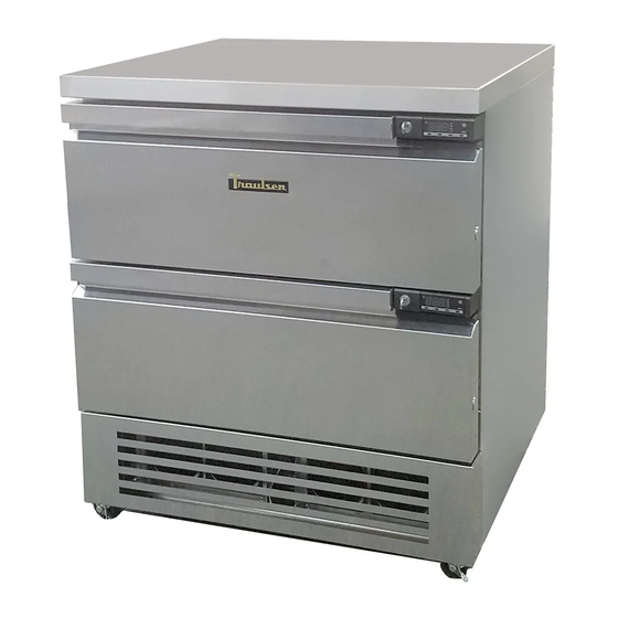
Convertible Two Drawer Refrigerator/Freezer*
*Please Note: This manual is intended for use with the above referenced equipment manufactured after May 01, 2020.
4401 Blue Mound Road Fort Worth, Texas 76106 (USA)
Phone: 800.825.8220 | Service Fax: 817.740.6757 | E-mail: service@traulsen.com | Website: www.traulsen.com
Hours of Operation: Monday - Friday 7:30 a.m. - 4:30 p.m. (CST)
Advertisement
Table of Contents

Related Manuals for Traulsen Flexdrawer TF031D3


Summary of Contents for Traulsen Flexdrawer TF031D3
- Page 1 *Please Note: This manual is intended for use with the above referenced equipment manufactured after May 01, 2020. 4401 Blue Mound Road Fort Worth, Texas 76106 (USA) Phone: 800.825.8220 | Service Fax: 817.740.6757 | E-mail: service@traulsen.com | Website: www.traulsen.com Hours of Operation: Monday - Friday 7:30 a.m. - 4:30 p.m. (CST)
-
Page 2: Table Of Contents
• Model = The model # of your Traulsen unit Hi Press. (PRESH): 500psi 3.45 MPa (3,45 Mpa) Hi Press. (PRESH): • (S/N) Serial Number = The permanent ID# of your Traulsen unit Lo Press. (PRESL): 250 psi 1.72 Mpa (1,72 Mpa) Lo Press. (PRESL): •... -
Page 3: Receipt Inspection
III. d - CORD & PLUG All Traulsen models are supplied with a cord & plug attached. III. INSTALLATION It is shipped coiled and secured by a nylon strip to the back of the cabinet near condensing unit area. For your safety and III. -
Page 4: Operation
IV. OPERATION IV. OPERATION IV. b - FREEZERS (cont’d) Both refrigerators and freezers do not require manual coil enclosure to prevent any significant rise in temperature defrosting. However, manual defrost option is available on within the food zone. The fan delay control function upon the control, if required. termination of a defrost cycle is two-fold. First, to prevent blowing warm air into the food storage area. -
Page 5: E) Drawer Loading
IV. OPERATION (continued) V. CARE & MAINTENANCE (continued) IV. e - DRAWER LOADING V. c - CLEANING THE CONDENSER FAN GUARD Product should be placed in a way that ensures air can The condenser fan guards are functioning as filter in this circulate. Do not operate without the ABS bin in place (see cabinet. -
Page 6: G) Drawer Gasket Replacement
V. g - DRAWER GASKET REPLACEMENT VI. a CONTROL BASICS To remove the gasket to be replaced, grasp it firmly by Your new Traulsen unit is equipped with a digital control, one corner and pull it out. Before attempting to install a which precisely regulates operation. It is supplied from the new gasket, both the unit and gasket must be at room factory completely ready for use. -
Page 7: B) Adjusting Cabinet Setpoint
VI. CONTROL BASICS VI. a INFORMATION MENU (cont’d) VI. c - INITIATING A DEFROST (cont’d) Selection of Second Parameter Group: Manual or remote defrost start: It’s possible to select control parameters between It’s possible to manually start a defrost, by pressing button two different pre-programmed groups, in order for the for 2 seconds. -
Page 8: D) Configuration Parameters
VI. CONTROL BASICS VI. d - CONFIGURATION PARAMETERS Parameter Configuration: • To get access to the parameter configuration menu, press button for 5 seconds. • With button select the parameter to be modified. • Press button to display the value. • By keeping button pressed, use button set the desired value. - Page 9 VI. CONTROL BASICS (continued) RANGE DESCRIPTION -58..SPH Minimum limit for SP setting. SPL...180° Maximum limit for SP setting. SPL... SPH Setpoint (value to be maintained in the room). REF; HEA Refrigerating (REF) or Heating (HEA) control mode. 1...10° Thermostat OFF -> ON differential. 0...10°...
- Page 10 VI. CONTROL BASICS (continued) RANGE DESCRIPTION Defrost display mode. During defrost the display will show: RT: the real temperature; LT : the last temperature before defrost; SP : the current setpoint value; DEF : “dEF”. 0...60min Display delay. The display shows the information selected with parameter DDM during defrost and for DDY minutes after defrost termination.
- Page 11 VI. CONTROL BASICS (continued) RANGE DESCRIPTION IIH1 0... 10° Thermostat ON->OFF differential in mode 2. IIDF 0...250 Time interval among defrosts in mode 2 in x10 minutes. IIFC NON; Fan control in mode 2. See FCM. TMP; 1...5 Controller sensitivity for the automatic switchover from Group I to Group II (1=minimum, 5=maximum). 1…5 Controller sensitivity for the automatic switchover.
- Page 12 VI. CONTROL BASICS (continued) RANGE DESCRIPTION NON; AUX 1 output operation LGT; NON : output disabled (always off). 0-1; LGT : output enabled for light control. 2CU; 0-1 : the relay contacts follow the on/standby state of controller. 2EU; 2CU : output programmed for the control of an auxiliary compressor. ALO;...
-
Page 13: F) Componets And Wiring Diagram
VI. CONTROL BASICS (continued) VI. e - TECHNICAL DATA (cont’d) VI. f - COMPONENTS AND WIRING DIAGRAM (cont’d) Control Wiring Diagram: EPT Parameter Fig. 6 VI. f - COMPONENTS AND WIRING DIAGRAM Indications: Thermostat output Fan output Defrost output Activation of 2 patameter set Alarm Manual activation / Increase button... -
Page 14: Troubleshooting Guide
VII. TROUBLESHOOTING GUIDE VII. a -TROUBLESHOOTING GUIDE FIND YOUR PROBLEM HERE REMEDY a.Check if cord & plug has been disconnected. 1. Condensing unit fails to start. b.Check control temperature setting. a.Are doors closing properly? 2. Condensing unit operates for prolonged periods or b.Dirty condenser or filter. Clean properly. -
Page 15: Service/Warranty Information
Is the fuse OK or circuit breaker on? Is the condenser coil clean? Is the power switch on? If after checking the above items and the unit is still not operating properly, please contact an authorized Traulsen service agent: Traulsen 4401 Blue Mound Road Fort Worth, TX 76106 (800) 825-8220. - Page 16 Purchaser. In the case of a nonconforming part, Purchaser must return the part to Traulsen within 30 days from the date of repair. Failure to return a claimed defective part to Traulsen within the 30 days will waive the right to the warranty claim.
- Page 17 NOTES: -16-...
- Page 18 4401 Blue Mound Road Fort Worth, Texas 76106 (USA) Phone: 800.825.8220 | Service Fax: 817.740.6757 | E-mail: service@traulsen.com | Website: www.traulsen.com Form Number: TR36229 | Part Number: TR36230 | Revision Date: 05-01-20 Traulsen © All Rights Reserved...
- Page 19 Purchaser. In the case of a nonconforming part, Purchaser must return the part to Traulsen within 30 days from the date of repair. Failure to return a claimed defective part to Traulsen within the 30 days will waive the right to the warranty claim.
Need help?
Do you have a question about the Flexdrawer TF031D3 and is the answer not in the manual?
Questions and answers