Table of Contents
Advertisement
Advertisement
Table of Contents

Related Manuals for Amcrest NV2104

Summary of Contents for Amcrest NV2104
- Page 1 Network Video Recorder User Manual Version 1.0.5 Revised November 23 , 2020...
-
Page 2: Table Of Contents
UPNP ............................62 Email ............................63 Multicast ..........................65 Register ..........................66 Switch ............................. 67 P2P ............................67 Amcrest View Pro Setup ......................68 Storage ........................... 71 Basic ............................71 Schedule ..........................71 HDD Manager ......................... 75 Record ............................ 75 Advanced .......................... - Page 3 Security ........................... 83 Account ........................... 84 User ............................85 Group ............................86 ONVIF User ..........................87 Password Reset ........................88 Live ............................89 Playback ..........................90 Alarm ............................94 Alarm Info ..........................94 Alarm Input ..........................95 Alarm Output .......................... 97 Video Detection ........................
-
Page 4: Welcome
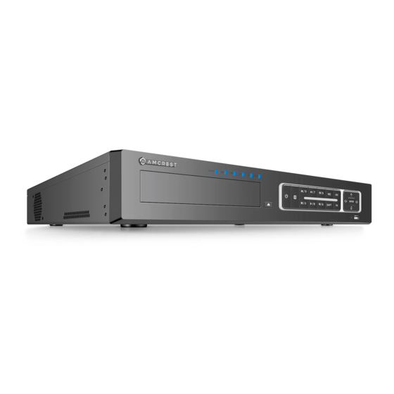
Thank you for purchasing an Amcrest NVR! This user’s manual is designed as a reference tool only and is applicable to all Amcrest 2000, 4000, and 5000 Series model NVRs. Please note, some features and options may vary model to model. - Page 5 Install in a well-ventilated place; do not black the vents. Front Panel The front panel of the NVR may differ model to model. Below is a representation of the front panel for all applicable NVR devices. Applicable for the NV2104/NV2104E/NV2108/ NV2116/NV2108E/NV4108E-HS/NV4116E-HS Icon Name Function...
- Page 6 Network abnormal Network error occurs or there is no network indicator connection, the light becomes red to alert you. Remote control When the NVR receives a signal from the remote, indicator the light will blink. POWER Power indicator When NVR is on, the light is on. Go to previous menu or cancel current operation.
- Page 7 Left/2 Right/3 Shift current activated control. Go to previous menu or cancel current operation. When playback, click it to restore real-time monitor mode. Applicable for Amcrest 52XXX Series NVRs Button Icon Description Power Button Press and hold this button for five seconds to shut off or power on the NVR.
- Page 8 Multiple slow play speeds or normal playback. In text mode, input Slow Motion/8 number 8. In playback mode, press to playback the next video. In menu setup, go Next/9 downward in a dropdown list. In text mode, input number 9. In playback mode, press this button to playback the previous video.
- Page 9 HDMI High High definition audio and video signal output port. Definition It transmits uncompressed high definition video and multiple- Media channel data to the HDMI port of the display device. HDMI version is Interface 1.4. VGA video VGA video output port. Outputs analog video signal. This connects to output port the monitor to view analog video.
-
Page 10: Hardware Setup
NVR. If a microSD card is installed in the camera you can still view the recordings from the microSD card using the Amcrest View Pro application and accessing the camera directly, however, no recordings will be retained to the NVR if a hard drive is not installed. - Page 11 For further assistance on how to install the hard drive, feel free to contact us at: https://amcrest.com/contacts Setting Up the Cables The following instructions will show you how to set up the cables for the NVR, cameras (PoE and Wi-Fi), as well as a monitor or TV screen.
- Page 12 Connect a monitor or TV screen to your NVR. The NVR is compatible with any monitor or screen that uses a VGA or HDMI connection. For purposes of this guide, we will use a VGA connection. Take a VGA cable, and connect one end to the VGA port on your monitor/screen and the other end to the VGA port on the back panel of your NVR.
- Page 13 Figure 2-6 Icon Function 1, 2 ALARM1, ALARM2. The alarm becomes activated in the low level. NO C NO activation output. (On-off button). +12V Rated current output. Current is 500mA. Ground Note Different models support different alarm input ports. Please refer to the specifications sheet for detailed information.
-
Page 14: Audio Ports
An overload may result in NVR damage. Please refer to the following relay specifications for detailed information. Alarm relay specifications Contact Material Silver Rated switch capacity 30VDC 2A, 125VAC 1A Rating Maximum switch power 125VA 160W (Resistance Load) Maximum switch voltage 250VAC, 220VDC Maximum switch current Between contacts with same polarity... -
Page 15: Device Installation
Mouse Operation Please refer to the following sheet for mouse operation instructions. Left mouse When you have selected one menu item, left mouse click to view the menu click content. Modify a checkbox or motion detection status. Click a combo box to show the dropdown list In an input box, you can select different input methods. - Page 16 Enter Password Create a new admin password for your NVR. The password for your device should be between 8 and 32 characters. A combination of letters, numbers, and symbols are recommended when setting up your password. Note: Please do not use special symbols like ‘ ‘ ; : & Once you have entered a new password for your device, confirm the password in the next field.
- Page 17 If you have assigned an unlock pattern, you will need to draw the pattern again to confirm your assigned unlock pattern. Password Protection Additional means of password protection and retrieval can be set up in this menu. If you would like to reset your password using your email, make sure the email address checkbox is enabled and enter a valid email address in the Email Address field.
- Page 18 The first page of the Startup Wizard will appear which allows you to setup any General, Network, Remote Devices, and Record Control Settings for the NVR. Before proceeding please note, most Amcrest products are H.265 compatible. H.265 provides a more advanced technology than H.264 and allows the device to reduce file sizes which in turn helps to reduce required bandwidth without sacrificing frames per second (FPS) or resolution.
- Page 19 Once you are satisfied with the settings on this screen click Next to continue. Date & Time The Date & Time settings screen is used to set the date and time for your NVR. If you want to utilize daylight savings time, click on the DST enable toggle switch. This should be enabled by default.
- Page 20 Note: Make sure to toggle the NTP toggle switch to the off position if you do not want to sync your device to an NTP server. Holiday This screen allows the user to set and modify holiday settings which allows the NVR to record or send snapshots based on specific schedules set by the user.
- Page 21 The next screen that appears is the P2P screen. This screen allows you to connect your NVR to your mobile device via the Amcrest View Pro app. The P2P status should read as “Online”. To download the app, use your mobile device’s camera and scan the Cell Phone Client QR code.
- Page 22 Click the Next to continue. Camera Registration The next screen that appears is the Camera Registration screen. This is where you can begin adding cameras to the NVR. If the cameras are not directly connected to the back of the NVR, please make sure they are active and on the same network as the NVR before proceeding.
- Page 23 A list of applicable connected devices will show on the screen. Select your devices by clicking on the checkbox next to the device and click Add to add the device into the Added Devices menu. If the status of your camera is red, it indicates the camera is not properly connected to the NVR. This could be because the password for the camera is not entered properly in the system.
- Page 24 To modify the password for your camera, click on the edit icon (pencil) located in the Edit column in the Added Device menu. Select the Password field and use the onscreen keyboard to enter the password for your camera. Once the password has been entered, click Connect then click Save to continue.
- Page 25 H.265 compression. Switching to H.265 compression reduces bandwidth without sacrificing frames per second or resolution. To activate H.265 compression, click on the H.265 Auto Switch. For more information on H.265 compression, please visit: amcrest.com/support Click on Next to proceed.
- Page 26 The next screen you will see will be the video wall screen which will display all connected devices. Right click on the video wall and click on the ‘Main Menu’ from the selections to access the main menu. Main Menu Overview The screenshot below is the main menu screen for the Amcrest NVR console interface:...
- Page 27 Adjusting Camera Settings for Maximum Resolution, FPS, and Bitrate Most Amcrest products are H.265 compatible. H.265 provides a more advanced technology than H.264 and allows the camera to reduce file sizes which in turn helps to reduce required bandwidth without sacrificing frames per second (FPS) or resolution.
- Page 28 our H.265 compatible products will come factory default to H.264. For optimal performance, the device's settings can be upgraded to H.265 compression if needed. Please note, for higher performance as well when using H.265 compression it is recommended to adjust bitrate. The bitrate is the number of bits that are processed per unit time by the system and helps the system to create a tradeoff between bandwidth and image qualit y .
- Page 29 Click Apply to save your settings. Adjusting Bitrate Since H.265 compression uses roughly 30% less resources than H.264, the camera will typically come defaulted to a preset bitrate when switching to H.265. For instance, when switching to H.265 on a 4K camera, the bitrate may be defaulted to 8192 Kb/S, however, adjusting the bitrate to a lower value may help to increase the overall efficiency of the camera while viewing playback or watching live view.
-
Page 30: Video Wall
Note: Adjusting the bitrate to anything lower than the recommended bitrate s above may result in degradation to recordings or to live view. For best results, if you are adjusting multiple cameras, it is highly recommended to adjust each camera individuall y . This may be a trial and error process since most network environments are unique and may vary, however, the bitrate should range between 1792-2048 Kb/S if using a 4K camera. - Page 31 Move the mouse to the top center of the video of the current channel, and the system pops up the preview control interface. If your mouse stays in this area for more than 6 seconds and preforms no operation, the control bar automatically hides. Instant Playback Click this button to instantly playback any previous motion detection events that were captured by the camera.
- Page 32 This will take you to a camera registration screen. Click on Device Search or Manual Add to begin adding the device. If using Device Search, please make sure the camera is on the same network as the NVR before searching. Once the camera has been detected, click on the device to highlight it, and click Add. Please note, if the device is not registering to the device, the username or password may need to be updated for the camera.
- Page 33 In the registration screen, click on the Edit icon (pencil) and ensure the username and password are correct and click Connect. Once this is verified click Save. The status indicator for the camera should turn green, indicating the camera has been added successfully. Note: For maximum compatibility when accessing your camera in a web browser or third party applications, our H.265 compatible products will be factory defaulted to H.264 but for increased performance, the camera's settings can be upgraded to H.265 compression.
- Page 34 H.265 compression, click on the H.265 Auto Switch to switch the camera to H.265 compression. For more information on H.265 compression, please visit: amcrest.com/support Please note, H.265 compression is only compatible with 4000 series and above NVRs and may not be applicable to certain devices such as 2000 series or below NVRs.
- Page 35 PTZ: Click this option to access the pan/tilt/zoom interface. Please note, this option is only applicable if a PTZ device is connected to the NVR. PTZ allows you to control the PTZ direction, speed, zoom, focus, iris, preset, tour, scan, pattern, aux function, light and wiper, rotation, etc. Full Screen: Click the full screen option to display a selected feed in full screen.
- Page 36 Right mouse click or click the ESC button on the front panel to go back Icon Function Icon Function Preset Auto Pan Tour Flip Pattern Reset Auto Scan PTZ Settings Call PTZ Function Preset Input the Preset value and then click to call a preset.
- Page 37 Click the box next to Preset and then input the preset number. Click the Set button to save the current preset. Tour Setup Click the Tour tab. Input tour value and preset No. Click the Add preset button to add the current preset to the tour.
- Page 38 Scan Setup Click the Scan button. Use the direction buttons to set the camera’s left limit and then click the Left button. Use the direction buttons to set the camera’s right limit and then click the Right button. Now the scan setup process is complete.
-
Page 39: Web Operation
Google Chrome, Firefox, Safari and other mainstream web browser via your PC or Mac computer. However, as a primary means of accessing the web user interface for your Amcrest device in a web browser, we highly recommend using Internet Explorer to access your device's web user interface. -
Page 40: Main Menu
New Password field and confirm. The password used should be between 8 and 32 characters long with a combination of letters and numbers. Click OK. The main menu for the NVR will be displayed. If the process above is not working, please contact Amcrest Support via one of the following options: Visit http://amcrest.com/contacts... -
Page 41: Camera
Below are short descriptions for each of the menu items on the main menu: LIVE: View real-time video via the live view interface. PLAYBACK: View, search, and play recorded videos. ALARM: View and search live alarm information. Configure alarm event actions. OPERATION: View system information, system updates. - Page 42 PoE port on the back of your device the camera will be automatically registered. However, please ensure the password for the camera is registered properly in the system to function. The default password for most Amcrest IP cameras is “admin. To begin registering a camera, click on Device Search.
- Page 43 Select the device from the interface and click Add to add it into the system. Once the camera has been added into the interface, click on Edit. This menu allows you to edit camera related information and verify the camera has the proper username and password in the system. Once the camera has been added properly, the status field will read “green”...
-
Page 44: Image
Upgrade This tab allows the user to upgrade the firmware for their camera directly from the NVR. Below is a screenshot of this menu: Below is an explanation of the fields listed in this menu: Channel: Indicates the channel number of the camera being monitored. Status: Indicates the connection status of the camera. - Page 45 The following options will vary depending on camera model and manufacturer Channel: Select a connected device from the channel dropdown list. Config File: This dropdown menu allows the user to set a config file for image settings. Saturation: This is to adjust the monitor window saturation. The value ranges from 0 to 100. The default value is 50.
-
Page 46: Encode
Gamma: This threshold value changes image brightness via nonlinear method and improves dynamic display range. The higher this value, the brighter image will be and vice versa. The value ranges from 0 to 100. The recommended value ranges from 40 to 60. The default value is 50. Mirror: This is to flip the video horizontally (as if looking in a mirror). - Page 47 Channel: This dropdown box allows the user to select a channel from the dropdown list to modify. Smart Codec is a function in most Amcrest cameras which aim to reduce bandwidth consumption without losing visible image quality by intelligently increasing compression where it will not make a visible difference in the scene.
- Page 48 H.265 provides a more advanced technology than H.264 and allows the device to reduce file size which helps to reduce required bandwidth without sacrificing frames per second or resolution. Most Amcrest products, such as, our NVRs, are H.265 compatible however, please note, H.265 compression is only an available on 4000 series and above NVRs and may not be applicable to any NVRs 2000 series or below.
- Page 49 Step 4: Click Save to save your settings. Please note, if you are using a camera with a built-in microphone the microphone may be disabled by default. This is due to specific guidelines which regulate built-in microphones to be enabled by default in certain areas and may need to be enabled manually to function.
- Page 50 How to Enable Audio for an IP Camera Using an NVR Due to specific regulations most IP cameras sold by Amcrest that feature a built-in microphone will have the microphone disabled by default. These options however can be enabled manually by using the IP camera's and NVR's web user interfaces (web UIs) using a common web browser.
- Page 51 The web UI for your connected camera will be displayed. Enter the password for your camera and click Login to access the interface. Please note, if your camera is not supported in the web browser you are using, please try another main stream browser such as Google Chrome, etc.
- Page 52 Navigate back to the web UI for your NVR and click on Encode. Ensure the proper channel is selected in the interface and click on the More Setting button in the Main Stream column to access audio options. Ensure the Audio Enable checkbox is enabled and click Save. Ensure the same settings are enabled for the sub stream side as well.
- Page 53 Snapshot This tab allows for the selection of snapshot settings. See below for a screenshot of the Snapshot tab: Below is a list of snapshot settings that can be modified on this screen: Channel: This dropdown box allows the user to select a channel from the dropdown list to modify. Mode: There are 2 snapshot modes, timing, and trigger.
- Page 54 Image Size: This dropdown box allows the user to select an image size. This may be unavailable (grayed out) on certain models. Quality: This dropdown box allows the user to select image quality. Quality is adjusted on a scale between 1, being the lowest quality and 6 being the highest quality. Interval: This dropdown allows the user to select the snapshot interval.
-
Page 55: Ptz
Clicking the set button and allows the user to drag the timestamp to the desired position on the screen. Customize Title: This checkbox allows the user to add customized text to the interface. Font Size: Set small, medium, or large text. Align Mode: Align the text left or right in the text box. -
Page 56: Network
To revert to default settings, click the Default button near the bottom left-hand corner. To confirm the settings, click the Save button. Network This menu controls all network related functions for the NVR and governs how the NVR interacts with a connected network. -
Page 57: Connection
gateway; the MTU of the NVR should be the same or lower than the MTU of the gateway. This way, packets can be reduced, and the network transmission efficiency be enhanced. The following MTU values are for reference only. 1500: Ethernet information packet maximum value and it is also the default value. It is the typical setup when there is no PPPoE or VPN. - Page 58 Below is an explanation of the fields on the Connection screen: Maximum Connection: This field represents the maximum number of users that can be connected to the NVR at the same time. The maximum number of users the NVR can support at one time is 128. TCP Port: This field designates the Transmission Control Protocol (TCP) port number.
- Page 59 The HTTPS cert will need to be created, log into the device and access the HTTPS menu. Click on the Create Server Certificate button. Enter the necessary credentials for your HTTPS certificate and click Create.
-
Page 60: Pppoe
The browser will reset again and will automatically load the login interface. You will notice the IP address has changed to HTTP and the security report will show a lock symbol indicating the cert has been created properly. PPPoE PPPoE stands for Point-to-Point Protocol over Ethernet. This screen allows users to configure PPPoE connections. -
Page 61: Ddns
Input the PPPoE username and password you get from the IPS (internet service provider) and enable PPPoE function. Please save current setup and then reboot the device to get the setup activated. Device connects to the internet via PPPoE after reboot. You can get the IP address in the WAN from the IP address column. -
Page 62: Upnp
Below is an explanation of the fields that can be configured on DDNS settings screen when set to AmcrestDDNS type. Fields with a ‘*’ next to them appear when AmcrestDDNS is selected: Enable: This option allows the user to enable DDNS on the NVR. DDNS Type: This dropdown box allows the user to select which DDNS service is being used on the NVR. -
Page 63: Email
PAT: PAT stands for Port Address Translation, and it is something that the UPnP protocol handles. This checkbox allows the user to enable UPnP on the device. Status: This field shows the UPnP status and has two options: Offline: This means that UPnP is offline. Successful: This means that UPnP is working. - Page 64 Below is an explanation of the fields on the Email settings screen: SMTP Server: SMTP stands for Simple Mail Transfer Protocol. This field allows the user to enter the SMTP server used by the email service. Port: This field allows the user to enter the port that corresponds to the selected SMTP server. Username: This field allows the user to enter the username used to login to the selected SMTP server.
-
Page 65: Multicast
This helps to curb heavy load on the email server when multiple events are occurring. For more information on how to setup Email Alerts, please visit amcrest.com/support Click on the Test button to test the connection. Click the Refresh button to refresh the interface. To confirm settings, click the Save button. -
Page 66: Register
ff02::6 OSPFv3 All DR routers ff02::8 IS-IS for IPv6 routers ff02::9 RIP routers ff02::a EIGRP routers ff02::d PIM routers ff02::16 MLDv2 reports (defined in RFC 3810) ff02::1:2 All DHCP servers and relay agents on the local network segment (defined in RFC 3315) ff02::1:3 All LLMNR hosts on the local network segment (defined in RFC 4795) ff05::1:3... -
Page 67: Switch
The P2P screen allows users to access a QR code to connect their smartphone or tablet to the NVR. The device uses an app called Amcrest View Pro, and it is available on both iOS and Android. Below is a... -
Page 68: Amcrest View Pro Setup
Click the Refresh button to refresh the interface. To confirm settings, click the Save button. Amcrest View Pro Setup The Amcrest View Pro app allows instant access to all live camera streams from any location. The app supports a multitude of features and includes both a plug-and-play setup as well as a manual network setup. - Page 69 Download and install the Amcrest View Pro app for the App Store or Google Play Store. Open the app on your mobile device and allow the app to load.
- Page 70 6. Scan the QR code. The QR code can be found on the serial tag along with a Note: IP/Domain/DDNS can be used to scannable barcode. establish a DDNS connection. For more information on how to setup a DDNS connection, visit amcrest.com/support...
-
Page 71: Storage
7. Create a name for the device and 8. Update the default password for the device and tap “Start Live View” to view enter a username and password. The the device. default username and password will be admin. Tap “Start Live View”. Storage This menu allows the user to update, modify, and manage device storage settings within the NVR. - Page 72 Below is an explanation of the fields on the Record settings screen: Channel: This dropdown box allows the user to pick which channel they would like to change video recording settings for. ANR: This option is used to allow the device to save video to the SD card of the network camera in case the network connection fails.
- Page 73 Click the text next to each period to edit the time you wish to set for that specific period. Next, choose which record type you would like to set for each period. You will also need to select the days you wish to apply these settings.
- Page 74 Below is an explanation of the fields on the Snapshot settings screen: Channel: This dropdown box allows the user to pick which channel they would like to change video recording settings for All: Link all days of the week to a selected recording type schedule. Record Types: There are 5 types of recordings: Regular: Regular recording means that the NVR captures all snapshots for the specified time period.
-
Page 75: Hdd Manager
HDD Manager This screen is used to help the user monitor the NVR’s hard drives. Using this screen, the user can see the current HDD type, status, and capacity. The user can also use this screen to format hard drives and change hard drive properties. -
Page 76: Advanced
Below is an explanation of all the fields on the Record settings page: Main Stream: The main stream is the stream through which the channels transmit data by default. There are 3 settings that can be used for the mainstream. Auto: Channels will record as they have been scheduled, and not in any other capacity. - Page 77 This tab allows the user to set HDD groups and setup operations for mainstream, sub stream, and snapshot operations. Note: This feature may not be available in all models and may be applicable to only certain model NVRs. Main Stream The Mainstream interface allows the user set corresponding HDD group to save to the mainstream configuration of a connected device.
-
Page 78: Ftp
Use the HDD Group dropdown menu to set all the channels to a specific HDD group. To apply all channels, click All. To save the settings to the device click on Save. To copy settings to another channel, click Copy near the bottom left hand corner. To confirm settings, click the Save button. - Page 79 Channel: This settings button allows the user to select a channel in which the FTP will apply. For more information how to setup FTP settings, please visit amcrest.com/support To revert to default settings, click the Default button near the bottom left hand corner. To test the...
-
Page 80: System
System General This screen displays general settings for the NVR. Below is a screenshot of the general settings screen: Below is an explanation of the fields on the General settings screen: Device Name: This field allows the user to customize the name of the NVR. Device No: This field allows the user to customize the device’s number. - Page 81 Date and Time This screen displays date and time settings for the NVR. Below is a screenshot of the Date & Time settings screen: Below is an explanation of the fields on the Date & Time settings screen: System Time: This field allows the user to set the system time and time zone. Click Save to save the system time as it is shown in the display.
- Page 82 / Forward Slash _ Underscore Time Format: This dropdown box allows the user to specify a time format for the NVR to use. There are two options. 24 Hour 12 Hour DST: This option allows the user to activate DST for the system. DST Type: This field allows the user to pick whether DST starts on a specific day of the week, or on a specified.
-
Page 83: Security
Below is an explanation of the fields on the Holiday settings screen: 0: This number indicates how many holidays are in the system. Each line item has a number to signify its place in the list. Status: This dropdown box indicates the status of the holiday. There are two options: Open: The holiday is active, and the NVR will stop recording for that holiday period. -
Page 84: Account
Below is a description of the fields in the security settings screen: Type: This dropdown menu allows the user to select which type of firewall will be included. There are 3 types of firewall settings. Network Access: Prevents a set IP address from network access. Ping Prohibited: Prevents the device from pinging a set IP address. -
Page 85: User
User This screen is used to configure User account settings. Below is a screenshot of the User Account settings screen: Below is an explanation of the fields on the User screen: Number: This number indicates how many users are in the system. Each line item has a number to signify its place in the list. -
Page 86: Group
Note: It is recommended to give the general user fewer rights than an administrative one. When a new user is created, a MAC address can be entered for the user. This can limit the user's ability to logon from another device. If left blank, the user can logon from any MAC address. There is a total of 98 rights that can be assigned to a user. -
Page 87: Onvif User
ONVIF User This screen is used to configure or modify ONVIF users that are associated with your NVR. Below is a screenshot of this menu: Below is a description of the fields listed in this menu: Number: This number indicates how many users are in the system. Each line item has a number to signify its place in the list. -
Page 88: Password Reset
Password Reset This menu is used to add an email address in which the Forgot Password instructions can be emailed. Please ensure a valid email address is entered in this field. To confirm settings, click the Save button. Click the Refresh button to refresh the interface. -
Page 89: Live
Live The live view interface provides a real-time viewing of a connected device. Note: If using Google Chrome or other mainstream web browsers the sub stream for the device may be displayed in the interface by default. Please note, some older computers may not be able to support H.265 compression which may result in a corrupted file. -
Page 90: Playback
PTZ Menu: Used to configure PTZ presets. For more information on how to setup a PTZ preset, if applicable, please visit: amcrest.com/support Alarm Out: Enable or disable a set external alarm using an applicable alarm channel. W:H: Adjust the frame rate of the selected device. - Page 91 Please refer to the following sheet for more information. Playback Interface: The playback interface is where all searched video data will be displayed. The interface can support 1, 4, and 9 playback windows depending on the model. Search Type: This area allows the user to display video or snapshot events. Events from a MicroSD card (if one is installed on the camera side) can also be selected.
- Page 92 ■ Stop: Stops the recording Backward Play: Rewinds the recording. Click the ►/icon to resume play mode. Previous Frame: Returns the recording to the previous frame in playback mode. Next Frame: Moves the recording to the next frame while in playback mode. ...
- Page 93 Mark Playback Please make sure your purchased device supports this function. You can use this function only if you can see the mark playback icon on the Search interface. When you are playing back a record, you can mark the record when there is important information. After playback, you can use the time, or the mark key words to search the corresponding record and then play.
-
Page 94: Alarm
Alarm The Alarm menu allows the user to view live alarm information as well as configure alarm event actions such as motion detection. Alarm Info This feature allows the user to search for specific types of alarm information related to the system. These specific types of alarms include, Motion Detection, Video Loss, Tampering, Abnormalities, Local Alarms, Intel, etc. -
Page 95: Alarm Input
To use this feature, access the alarm info interface and select the type of alarm you are search for from the dropdown menu. Enter in the start and end times in the Start Time and End Time fields and click Search. - Page 96 ▪ N.C: Normally Closed - A Trigger that initiates when an object disrupts the communication line of 2 sensors ▪ N.O: Normally Open - A Trigger that initiates when an object completes the communication line of 2 sensors. 2. Connect the N.C. (Normally Closed) wire to one of the numbered ports. Connect the COM wire to the COM / Ground Port.
-
Page 97: Alarm Output
Normally Closed: (NC) A Trigger that initiates when an object disrupts the communication line of 2 sensors. Normally Open (NO): A Trigger that initiates when an object completes the communication line of 2 sensors. 5. Configure the alarm trigger settings. Click Save. ▪... -
Page 98: Video Detection
Manual: The alarm NVR is forced to keep generating alarms. Off: The alarm output function is not enabled. Status: The connection status of the alarm. Save: Click the Save button to release the alarm. For more information about the parameters listed in this menu, refer to the table provided below. Parameter Description Alarm Type... - Page 99 Below is a description of the fields on the Motion Detection settings page: Channel: The channel dropdown menu is used to select which channel you would like to use to set your motion detection. Region: The setup button takes the user to the motion detection region setup screen for that specific channel.
- Page 100 When the setup button is clicked, the current channel’s interface comes into a full screen view. The user can then set up to 4 regions, each with their own region name, sensitivity (1-100), and threshold (1-100). Each region has a specific color, and the region selector tool is displayed when the mouse is moved to the top of the screen.
- Page 101 to undo any changes and return to the motion detection settings screen. Click Default to use the default settings. The system allows for the configuration of up to 6 different time periods. Click the checkbox to the left of the time period to enable that time period. Click the text next to each period to edit the time period.
- Page 102 Below is a description of the fields on the Video Loss settings page: Channel: The channel dropdown menu is used to select which channel you would like to use to set your motion detection. Enable: This checkbox allows the user to enable the detection function for a specific channel. To select a channel, click on the drop-down menu provided on the right.
- Page 103 Click and drag on the yellow bars to specify time zones for detection. To edit multiple days at once, either click the checkboxes next to the names, or click the checkbox next to All to edit all the days at once.
- Page 104 Below is a description of the fields on the Tampering settings page: Channel: The channel dropdown menu is used to select which channel you would like to use to set your motion detection. Enable: This checkbox allows the user to enable the detection function for a specific channel. To select a channel, click on the drop-down menu provided on the right.
-
Page 105: Audio Detect
Click and drag on the yellow bars to specify time zones for detection. To edit multiple days at once, either click the checkboxes next to the names, or click the checkbox next to All to edit all the days at once. - Page 106 Below is a description of the features in this menu: Channel: The channel dropdown menu is used to select which channel you would like to use to set your motion detection. Input Abnormal: Interprets if an audio input is abnormal, such as clipping audio, etc. Intensity Change: Interprets if the intensity value surpasses the set threshold;...
-
Page 107: Abnormality
Tour: Allows the user to enable the camera to activate a PTZ tour when a motion detection alarm is triggered. PTZ Activation: Allows the user to active PTZ functionality to applicable PTZ devices. Voice Prompts: Check this box to enable an imported voice prompt to be used if an event occurs. To use this feature, select a file from the dropdown box in the File Name section. - Page 108 No HDD: No hard drive is detected. HDD Error: The hard drive has an error. HDD No Space: The hard drive is about to or has run out of space. Enable: This option allows the user to enable the features below for the specified event type. Alarm Out: Click Setting to display setting interface.
- Page 109 Net Disconnection: The network connection has been disconnected. IP Conflict: There is a device on the network with the same IP address. MAC Conflict: There is a device on the network with the same MAC address. Enable: This option allows the user to enable the features below for the specified event type. Show Message: This checkbox allows the user to enable the system to show an on-screen message when an abnormality occurs.
- Page 110 Alarm Out: Click Setting to display setting interface. General Alarm: Enable alarm activation through the alarm NVR connected to the selected output port. Alarm Out: Enable an alarm channel in which an external alarm is connected. Voice Prompts: Check this box to enable an imported voice prompt to be used if an event occurs. To use this feature, select a file from the dropdown box in the File Name section.
-
Page 111: Operation
Alarm Out: Click Setting to display setting interface. General Alarm: Enable alarm activation through the alarm NVR connected to the selected output port. Alarm Out: Enable an alarm channel in which an external alarm is connected. Voice Prompts: Check this box to enable an imported voice prompt to be used if an event occurs. To use this feature, select a file from the dropdown box in the File Name section. -
Page 112: Information
Type: Use this dropdown menu to select a log type. Start Time: The start time in which logged events will be displayed End Time: The end time in which a logged event will be displayed. Search: Run a query of logs based on the start and end time. Go To: Go to a specific log in the query. - Page 113 Running Status: Displays if the hard drive is active or inactive. The BPS tab allows the user to view current video bit rate (kb/s) and resolution provided for each connected channel. The menu will show the current channel and resolution of that specific channel. The kb/S section denotes the amount of kb/S used by that channel and the Wave menu shows, in wave format, the amount of kb/S used by that specific channels output.
-
Page 114: Network
The HDD Health Detection tab allows the user to view any errors associated with a connected hard drive. The interface can detect the name, amount of space left, the manufacturer, serial number, and current health status of the drive. Below is a screenshot of the interface: Below is a description of the fields listed in this menu: HDD State: Allows the user to filter specific types of errors All: Displays all errors detected. -
Page 115: System Maintain
No: The number assigned to the user in the system. Username: The username of the connected user. Group Name: The group name associated with the connected user. IP address: The IP address used by the connected user to access the system. User Login Time: The date &... - Page 116 Below is an explanation of the fields on the Config Backup settings screen: Export: Click this button to export all saved settings from the NVR to an inserted flash drive or to the computer if using the web user interface. The file will export as a “configFileExport.backup”...
-
Page 117: Back Up
USB storage device and plug it into the NVR. For more information on how to download a firmware file, please visit https://amcrest.com/firmware-subscribe Below is a screenshot of the upgrade screen: To begin upgrading the firmware, click on Download the latest Firmware and locate the firmware file for your specific device. - Page 118 Here is a brief explanation on how to use the backup feature listed in this menu: In the Path field, choose a file path in which the file will be backed up. This can be a local USB flash drive, if inserted locally or a folder path if using a web user interface.
-
Page 119: Display
Note: Click on the Watermark option to verify the watermark information assigned to the downloaded file. Display This menu allows the user to configure resolution and display setting outputs as well as setup a display tour if multiple displays are being used. Display This menu provides you with quick access to your display and output information associated with your NVR. - Page 120 Time Delay Enable and disables a time overlay in the output display. Channel Display Enable and disable a channel overlay in the output display. Image Enhance Enable and disable image enhancement settings of the output display. Original Rate Enable the default rate of a specific channel in the system. Click Default to set the display settings back to its original default settings.
- Page 121 Window Split: In the Window Split list, select View 1, View 4, View 8, or other modes that are supported by the NVR. Add: This button allows the user to add a channel to the tour. Delete: This button allows the user to remove a channel from the tour. Move Up: This button allows the user to move a camera up in the tour queue.
-
Page 122: Audio
In the modify channel group interface, select the group order for your selected group and click OK to complete the process. If you do not want to proceed with the modification, click the Back button to exit the modify group interface. Audio This function tile allows you to manage audio functions such as, audio file management and configuring audio playing schedules which can be associated with specific alarm events. -
Page 123: Remote Web Access
Schedule The schedule tab allows you to schedule downloaded audio to specific alarms in the device. Below is a screenshot of the schedule menu: For more information on the features listed in this menu, refer to the table provided below. Parameter Description Period... - Page 124 Once the main interface opens, click the plug icons next to each camera on the list on the left-hand side, and activate the mainstream for each of them to enable the live feed. If the process above is not working, please contact Amcrest Support via one of the following options: Visit http://amcrest.com/contacts...
- Page 125 Port Forwarding Remote Access Setup Port Forwarding is an alternative method to setting up remote access for your NVR. This method should only be used if the UPnP/DDNS Remote Access method did not work. Below is a step-by-step walkthrough that details how to setup the for Remote Web Access using UPnP: Login to your NVR, open the main menu then go to Management ->...
-
Page 126: Faqs/Troubleshooting
Once the main interface opens, click the plug icons next to each camera on the list on the left-hand side, and activate the mainstream for each of them to enable the live feed. If the process above is not working, please contact Amcrest Support via one of the following options: Visit http://amcrest.com/contacts... - Page 127 The hard drive is broken. • The hard drive cable is damaged. • The hard drive cable connection is loose. • The NVR's main motherboard SATA port is broken. 4. There is no video output on any of the channels. Below are a few possible reasons why this may be occurring: •...
- Page 128 • The microphone being used is not sufficiently powered. • The speakers being used are not sufficiently powered. • The audio cable is damaged. • The NVR hardware is malfunctioning. 9. There is no audio during recorded video playback. Below are a few possible reasons why this may be occurring: •...
- Page 129 • The client end computer is not compatible with the NVR's firmware. 14. Web Access live view is only displaying a static picture. Both live playback and recorded playback are not working. Below are a few possible reasons why this may be occurring: •...
-
Page 130: Fcc Statement
To contact Amcrest support, please do one of the following: • Visit http://amcrest.com/contacts and use the email form • Call Amcrest Support using one of the following numbers Toll Free: (888) 212-7538 International Callers (Outside of US): +1-713-893-8956 USA: 713-893-8956 Canada: 437-888-0177 UK: 203-769-2757 •... -
Page 131: Ic Warning Statement
which can be determined by turning the equipment off and on, the user is encouraged to try to correct the interference by one or more of the following measures: -- Reorient or relocate the receiving antenna. -- Increase the separation between the equipment and receiver. -- Connect the equipment into an outlet on a circuit different from that to which the receiver is connected. - Page 132 All the designs and software here are subject to change without prior written notice. All trademarks and registered trademarks mentioned are the properties of their respective owners. If you have any questions or concerns, please contact us at support@amcrest.com, or call us at 888212-7538.
Need help?
Do you have a question about the NV2104 and is the answer not in the manual?
Questions and answers