Table of Contents

Subscribe to Our Youtube Channel
Related Manuals for Axi STS 6000 P-35

Summary of Contents for Axi STS 6000 P-35
- Page 1 STS 6000 P-35 | 7000 P-35 Instruction, Operating, & Maintenance Manual ENCLOSED FUEL MAINTENANCE SYSTEM REV03016735010220 5400 Division Dr. | Fort Myers, FL 33905 239 690-9589 | Toll Free 877-425-4239 | FAX 239 690-1195 www.AXI-International.com...
- Page 2 REV03016735010220...
-
Page 3: Table Of Contents
Table of Contents Table of Contents ................................2 General Overview ................................4 STS 6000 P-35 | 7000 P-35 Specifications ........................4 System Components ................................5 Control and Safety Devices ..............................5 Fuel Conditioner ................................. 5 Primary Filter/Water Separator ............................5 Secondary Filter ................................. - Page 4 Warranty Claim Procedure ............................... 21 Technical Assistance and Ordering ..........................22 Accessories and Additional Configuration Parameters ....................22 Replacement Filter Elements ............................22 System Identification ................................ 22 REV03016735010220...
-
Page 5: General Overview
General Overview STS 6000 P-35 | 7000 P-35 Specifications Nominal Flow Rate…………………………………………….. 35 GPM/2,100 GPH (132.5 LPM/7,949.4 LPH) 16,800 gallons (63,595 liters) per 8-hour shift 50,400 gallons (163,530 liters) per 24-hour shift Primary Filter…………………………………………………… 1, 5, 10, or 25 Coalescing Filter Element Secondary Filters………………………………………………. -
Page 6: System Components
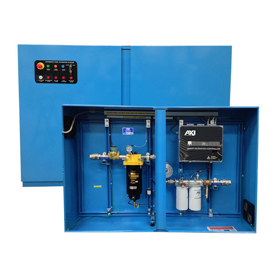
System Components Control and Safety Devices • System Controller Incorporated PLC-based Timer Memory retention during power outages Alarm Indicator Light(s) Control Circuit Breakers (CB1, CB2) Pump Control Selector Switch {Hand (Manual) / Off / Auto} Alarm Reset Push Button Pump Running Indicator Light System Power Indicator Light Emergency Stop (E-Stop) Push Button 6000 Series Controller:... -
Page 7: Manual Additive Injection - If Applicable
• Basket Strainer • Water Collection Drum High Water Level Float Switch If Applicable Manual Additive Injection – • System Ball Valve • Additive Injection Port • Injection Port Ball Valve If Applicable Auto Additive Injection Assembly – • Accessory Pump •... -
Page 8: System Operation
Note: If the Pump Overload Alarm triggers, please contact AXI International. Once triggered alarms are addressed, each alarm can be reset via the Alarm Reset button on the enclosure door panel. -
Page 9: Multi-Tank - If Applicable
If Applicable Multi-Tank – 1. From the Main Menu screen select “CONFIG” 2. Enter password (9999) 3. Enter the correct number of connected tanks in the box under “Number of Tanks”. 4. To see actual valve positions, select “VALVES” a. Press the “Open” and “Close” buttons to manually test the valves. If the “Open” or “Closed” rectangular box is GREEN, that status is active. -
Page 10: Auto Additive Injection - If Applicable
If Applicable Auto Additive Injection – 1. To start Auto Additive Injection, navigate from the Main Menu to the Additive Injection screen on the HMI. 2. On the screen there are two fields to input information, Gallons to Treat and Treatment Ratio. 3. -
Page 11: Primary Inspection
Primary Inspection Upon arrival, the system and accessories must be visually inspected before installation. Improper handling during shipping may cause physical or electrical problems. Immediately report or note any damages to the shipper. Checklist If the packing crate shows signs of damage inspect the system for damage. Check the entire system for damage that could indicate internal mechanical or electrical problems. -
Page 12: Installation
Installation Note: It is recommended that only qualified, experienced personnel, familiar with this type of equipment, who have read and understood all the instructions in this manual should install, operate, and maintain the system. Mounting The unit should be permanently wall mounted on a hard, level surface. Use provided mounting holes located on the enclosure for proper fastening (Refer to mechanical drawing(s) for Mounting Hole Diameter). -
Page 13: Typical Plumbing Installation (Schematically)
Use proper quality approved fuel line materials with similar inner diameter (ID) to the inlet/outlet of the system. For extended suction side plumbing runs, it is recommended to install oversized pipe, (1/4” to 1/2” increased ID). Note: Flexible plumbing is strongly recommended for system inlet and outlet connections to external plumbing in order to avoid issues with thermal expansion, prevent putting any stress on the internal fittings of the system, and enable ease of maintenance/installation. -
Page 14: Controller
Setting the Current Date and Time (7000 Series Controller) 1. Please make sure the pump is set to “OFF”. 2. On the home screen, long-press (for a few seconds) to the right of the AXI logo until a new screen appears. 3. Select ‘Enter Info Mode’. -
Page 15: Touchscreen Menu Structure (7000 Series Controller)
3. To set up a runtime simply enter a ‘Start’ and ‘Stop Time’ (using military format) in one of the timer boxes for the desired weekday. 4. To toggle between tanks (if applicable), simply press the available buttons on the bottom left or right hand side of the screen. -
Page 16: Commissioning/Initial Start-Up
The Inlet Solenoid Valve should close and the “Tank Overflow” alarm should be indicated on the System Controller. Reset the alarm by pushing the Alarm Reset button on the enclosure door panel. Note: If any of the above described alarm test procedures fail or if any alarm trip value deviates, immediately contact AXI International. -
Page 17: Maintenance
Maintenance The system should be visually inspected and tested a minimum of every six (6) months according to the procedure below during light duty cycles. Monthly inspections are recommended for systems that are being used in excess of an average of eight (8) hours a day and five (5) days a week. Preventative Maintenance Prior to performing the maintenance procedure ensure that: 1. -
Page 18: Servicing The Fine Filter(S)
12. Rotate the filter housing into the collar bolts and hand tighten the knobs until the head is “snug” to the housing. Note: A torque wrench is recommended. Tighten all collar bolts to 100 in lbs. 13. Close the drain valve at the bottom of the filter housing. 14. -
Page 19: Replacement Filter Chart
Replacement Filter Chart STS SERIES FILTERS All Filters are absolute, unless otherwise noted | wb: waterblock | SS: Stainless Steel Screen Primary Cartridge Filters 1µ 5µ 10µ 25µ WATER SEPARATOR FBO-60336 FBO-60337 FBO-60356 FBO-60338 SPIN-ON Filters 3µ 10µ 25µ 3µ X-Glass ParTICULATE FF-3 FF-10... -
Page 20: Troubleshooting
7. Discharge line clogged Note: The pump and motor assembly (as well as other ancillary plumbing/piping items such as foot or check valves) are generally not provided by AXI International. Therefore, AXI International does not assume responsibility for products provided by other vendors. -
Page 21: Axi International Limited Warranty
This warranty is not intended to supplant normal inspection, care and service of the products covered by the user, and shall not obligate AXI International to provide free service during the warranty period to correct breakage, maladjustment, or other difficulties arising out of abuse, misuse, or improper care and maintenance of such products. Our... - Page 22 AXI International reserves the right at any time to make changes in the design, material, function and specifications of its products. Any such changes shall not obligate AXI International to make similar changes in such products that were previously manufactured.
- Page 23 Fort Myers, FL 33905 Tel: +1-239-690-9589 Fax: +1-239-690-1195 Email: info@axi-international.com Internet: www.axi-international.com Please provide the following information: Serial Number of your system, the required part numbers and quantity. The drawings/parts list included in this manual are the most accurate source of part numbers.
Need help?
Do you have a question about the STS 6000 P-35 and is the answer not in the manual?
Questions and answers