Table of Contents
Advertisement
Quick Links
Technical Manual
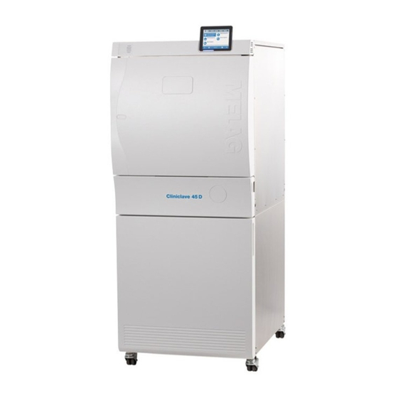
Cliniclave
Large steam sterilizer
from software version 3.218
EN
Read this manual carefully and in the correct order before setting up and commissioning the device. The instructions in-
clude important safety information. You also receive a user manual with the device. Please store this manual and the
user manual carefully and in close proximity to the device. They represent a component of the product.
®
45 D
Advertisement
Table of Contents

Related Manuals for MELAG Cliniclave 45 D


Summary of Contents for MELAG Cliniclave 45 D
- Page 1 Technical Manual ® Cliniclave 45 D Large steam sterilizer from software version 3.218 Read this manual carefully and in the correct order before setting up and commissioning the device. The instructions in- clude important safety information. You also receive a user manual with the device. Please store this manual and the user manual carefully and in close proximity to the device.
-
Page 3: Table Of Contents
Contents Contents 1 General guidelines ................................ 5 Symbols used.................................. 5 Formatting rules ................................... 5 2 Installation requirements.............................. 6 Installation material ................................ 6 Installation location................................ 8 On-side connections for installation ........................... 11 Space requirements ................................ 14 Safeguarding in accordance with EN 1717 ........................ 16 Checking the rotating field direction of the CEE socket ..................... 16 System and network safety .............................. 17 3 Setup and installation ................................ 19 Fitting the corner rails and centring rolls .......................... 19... - Page 4 Contents How do I determine the IP address or network setting of a computer (Windows 7/10)? ........... 45 What do the terms IP address, subnetwork and DHCP mean? .................. 45 How can I check the software version of the steam sterilizer? .................. 45 8 Technical tables ................................. 46 Feed water quality................................ 46 Precision and drift behaviour.............................. 47...
-
Page 5: General Guidelines
1 General guidelines 1 General guidelines Read this manual carefully and in the correct order before setting up and commissioning the device. The instructions include important safety information. You also receive a user manual with the device. Please store this manual and the user manual carefully and in close proximity to the device. They represent a component of the product. -
Page 6: Installation Requirements
2 Installation requirements 2 Installation requirements Installation material Installation set (art. no. 09027) for the water connections includes: Qty. Article Art. no. Surface-mounted siphon 72420 Rubber seal 3/4“ for external water supply 56950 Hose clamp Hanger bolt M8x60 Included in the scope of delivery of the steam sterilizer (and required for installation): Qty. - Page 7 2 Installation requirements Qty. Article Art. no. Casing panel, left, magnetic 84156 Casing panel, above, magnetic 84157 Casing panel, below, magnetic 84158 Drill head screws 3.5 x 25 mm Drill head screw 3.9 x 50 mm HSS drill bit N 2.5 mm Bit 1/4“ (Torx 10) Bit 1/4“...
-
Page 8: Installation Location
The steam sterilizer should only be setup, installed and commissioned by persons authorized by MELAG. The steam sterilizer is not suitable for operation in explosive atmospheres. The steam sterilizer is conceived for use outside the patient area. The device should be located a minimum of 1.5 m radius away from the treatment area. - Page 9 2 m wide. If it is not possible to install a drywall, the solenoid casing panels can be fitted on the solid wall. This requires consultation with MELAG. Requirements placed on the partition wall and the wall breakthrough...
- Page 10 2 Installation requirements Setting up the frame The width and the height of the frame depend on the strength of the drywall. The following dimensions ta- ble helps determine the correct dimensions for the wall breakthrough: Strength of the drywall Gs Wall breakthrough Width [x] Height [y]...
-
Page 11: On-Side Connections For Installation
Improper installation may lead to a short-circuit, fire, water damage or electrical shock. This could result in serious injury. Only have the device set up, installed and commissioned by people authorized by MELAG. Implement the following safety measures when dealing with the cable and power plug: Never damage or alter the power plug or cable. - Page 12 2 Installation requirements Never lead the cable along a source of heat. Never use any nails, paper fasteners or similar objects to fix the cable. Should the power plug or cable suffer damage, switch off the device. The power cable or plug should only be replaced by authorized technicians.
- Page 13 PLEASE NOTE The outlet hose must be fitted at a constant decline without kinks or sagging. Deviations to the installation arrangements require consultation with MELAG. Failure to do so can result in malfunctions of the steam sterilizer. The length varies, depending on the position from which the hoses are led out of the floor unit.
-
Page 14: Space Requirements
2 Installation requirements Space requirements View from the front, door hinge right on both sides Loading side Removal side The minimum clearances to be maintained on both sides in the area of the wall installation Dimensions Loading side Removal side Width 65 cm Width inc. - Page 15 The specifications correspond to the recommended installation of the outlet hose, i.e. if this is inserted in both tensioning carriages. Given deviating installation preconditions, please contact MELAG. It is imperative to ensure that the outlet hose is installed without kinks or sagging.
-
Page 16: Safeguarding In Accordance With En 1717
2 Installation requirements Safeguarding in accordance with EN 1717 The connection of the steam sterilizer to the water line is comparable with the connection of a washing ma- chine in a domestic context. In general, the connection of consumers to the drinking water supply should be performed in accordance with EN 1717, so that the drinking water supply is protected against contami- nation through the possible flow back of the water. -
Page 17: System And Network Safety
NOTICE When performing a device software update, use only the update data authorized by MELAG for the corresponding device type. Operating the device with memory media (CF card) To prevent data loss, only use memory media to save the log data with the following characteristics: Functional capability (without malware etc.) - Page 18 2 Installation requirements Operating the device in the local network (LAN) NOTICE Do not connect the device to a public network (e.g. the internet). An Ethernet/IP-based network connection (LAN) is required to operate the device in a local network. In its delivery state, the device is configured to obtain the IP address automatically from a DHCP server operat- ed in a LAN.
-
Page 19: Setup And Installation
Improper installation may lead to a short-circuit, fire, water damage or electrical shock. This could result in serious injury. Only have the device set up, installed and commissioned by people authorized by MELAG. Fitting the corner rails and centring rolls... - Page 20 3 Setup and installation Place at least one screw in each row of the drillholes in the corner rails to fix them. Use only the drillholes in which the screws have a secure purchase. PLEASE NOTE For ease of screwing, you can pre-drill 2.5 mm drillholes in the U-shaped bracing profile at the corresponding locations.
- Page 21 3 Setup and installation Fix the rails with screws in the same manner as on the loading side. Screw the second short corner rail to the upper frame edge of the removal side. Fitting the centring rolls Place the centring rolls on the locations marked on the corner rails with the screw head pointing upwards (see adjacent figure) and screw the centring rolls tight with four screws for each centring roll.
-
Page 22: Dispatch / Delivery
3 Setup and installation Dispatch / delivery CAUTION Danger of back injury and crushing from lifting excess loads. The steam sterilizer should be carried by at least six people. Comply with the safety regulations issued by your professional association. Depending on the transport route and method, the steam sterilizer and the floor unit will be delivered either screwed together or separately. - Page 23 3 Setup and installation PLEASE NOTE Recognizing the loading and removal side of the steam sterilizer and the floor unit: The fan at the top of the steam sterilizer always lies on the loading side. The door of the floor unit can only be opened on the loading side. Working with a minimum of six people, lift the steam sterilizer from the shipping pallet onto the floor unit so that the loading side of the steam sterilizer and the...
-
Page 24: Shielding The Clean Side
3 Setup and installation Screw the two plastic screws onto the removal side in the location on which the transport bars or carrying handles were previously screwed in (pos. a). Position the steam sterilizer in front of the wall breakthrough. The removal side of the steam sterilizer faces the wall breakthrough. -
Page 25: Aligning The Steam Sterilizer
3 Setup and installation Lock the casters on the floor unit. Unscrew the two remaining carrying handles on the loading side and replace them with the plastic screws. Aligning the steam sterilizer To align the steam sterilizer, it must be located in its final installation location. Align the steam sterilizer us- ing a spirit level so that it is plumb on all sides. - Page 26 3 Setup and installation Apply the upper casing panel with the seal on the upper side of the steam sterilizer and fit it between the two lateral cladding panels. Press the upper cladding panel with the magnetic strip on the upper corner rail until it clamps magnetically.
-
Page 27: Hose Connections For Over-Pressure Lines
12 or size 19) depending on requirements. Connecting the inflow and outlet hose PLEASE NOTE To prevent water damage, MELAG recommends the use of a leakage water detector e.g. the MELAG water stop. Install the leakage water detector (optional). Check whether the steam sterilizer is in its final position. - Page 28 3 Setup and installation Knocking out the circular recesses Two rows of drillholes are located on both sides of the floor unit (see following figure) each with three pre- cut large holes (pos. a) for the outflow and inflow hose and the power cable as well as a smaller hole (pos. b) for the network cable.
-
Page 29: Tensioning The Outlet Hose
3 Setup and installation Connecting the outlet hose Connect the outlet hose with one of the seals included in the scope of delivery to the steam sterilizer wastewater fitting (pos. e) in the floor unit. Lead the outlet hose laterally through the upper hole in the floor unit and to the outside. -
Page 30: Connecting The Network Cable (Optional)
3 Setup and installation Tighten the star knob (pos. c) in the first tensioning carriage and then the second. Check that the outlet hose has been installed without kinking and for the stability of the siphon to the wall next to the steam sterilizer. Connecting the network cable (optional) You can lead the network cable out of the loading or removal side and connect it to a computer (in the practice network) or a label printer. -
Page 31: Installing The Meladem 56 (Optional)
3 Setup and installation Introduce the network cable through the membrane grommet to the outside. Connect the network cable to the network socket/the label printer. Installing the MELAdem 56 (optional) Proceed as follows to connect the reverse osmosis unit and prepare rinsing: Loosen the screws (TX20) (pos. - Page 32 3 Setup and installation Do not yet remove the sealing cap on the feed water connection of the pressure tank (upper T-piece). Open the valve (pos. h) on the pressure tank and measure the primary pressure using the manometer included in the scope of delivery. The target pressure is 0.6 bar.
-
Page 33: Test Runs
4 Test runs 4 Test runs In order to reduce the installation time and ensure quicker commissioning of the steam sterilizer, a sepa- rate container with a min. 13 l feed water of sufficient quality (in accordance with EN 285, Appendix B, Ta- ble B.1) is required. - Page 34 4 Test runs Connect the power plug and switch on the steam sterilizer. The vacuum pump will run for a short while after activation. Directly during activation, check whether the silicone cap (marking) on the de-calcification connection contracts, i.e. suction. This indicates a correct direction of rotation.
-
Page 35: Bowie & Dick Test And Instruction
4 Test runs Connect the free end of the permeate line to the lower T-piece of the pressure tank (pos. a) and open the pressure tank shut-off valve (pos. b). The feed water connection (pos. c) on the upper T-piece of the pressure tank must remain closed for now. Place the pressure tank in the floor unit. -
Page 36: Operational Readiness
5 µS/cm. Operational readiness When using the MELAG water treatment unit From a pressure of 1.5 bar in the pressure tank, you can convert the feed water supply to the reverse os- mosis unit by proceeding as follows: Select menu Diagnosis &... -
Page 37: Checking The Pressure Of The Reverse Osmosis Unit
5 Operational readiness Close the pressure tank shut-off valve. Remove the cap from the feed water connection on the upper T-piece of the pressure tank. Store this cover cap carefully. Open the pressure tank shut-off valve and working in menu Settings > Device settings > Water supply set the feed water supply to YES, save the settings and leave the menu. -
Page 38: Settings And Adjustment
6 Settings and adjustment 6 Settings and adjustment Setting the door hinge In the delivery state, the opening angle of the door on the loading and removal side is approx. 95°. This can be set to any angle up to 170°. Working with a separate set of instructions “Setting the door hinge”... -
Page 39: Inserting The Shelf
6 Settings and adjustment Inserting the shelf You can insert the shelf (pos. a) at the desired height. Guide the hoses through aperture in the floor mat on the left-hand side. You can install the tool bracket (pos. b) in the mounting intended for this purpose. It can be used to store the carrying handles, the special key (hex for the casters) and the Allen key with which to open the door in an emergency. -
Page 40: Settings On The Steam Sterilizer
6 Settings and adjustment Guide both lateral display locking elements into the same guide groove on the steam sterilizer. Press the display downwards until you feel it engaging. Settings on the steam sterilizer Date and time Check the date and time and set if necessary. Consult the user manual. Display settings If required, working in the Settings menu, adjust the brightness, key tone and the touch-sensitivity. - Page 41 Further alterations to the program run are possible in each individual case and will still ensure the effectiveness of the sterilization, but may only be performed by authorized technicians. Please consult your stockist or MELAG. System and status log Output a system and status log and document this on the record of installation and setup.
-
Page 42: Frequently Asked Questions (Faq)
FAT16 or FAT32. CF cards from which a software update is to be per- formed may only be formatted in a FAT16 file system. The device can only file or read data on CF cards formatted in this way. CF cards supplied by MELAG fulfil these requirements and have already been formatted. -
Page 43: How To Integrate The Device In A (Practice) Network
Working in the (practice) network, determine which computer should run on the FTP server. If an FTP server has not yet been installed, install the MELAG FTP server for preference and set the steam sterilizer as user with a user name and password. - Page 44 7 Frequently Asked Questions (FAQ) 2. Connecting the network cable Connect the network cable to any network data connection of the device and connect it to the (practice) network (see Connecting the network cable (optional) [} page 30]). 3. Adjusting IP addresses in the steam sterilizer NOTICE The setting up in the (practice) network will require in-depth understanding of the network technology.
-
Page 45: How Do I Determine The Ip Address Or Network Setting Of A Computer (Windows 7/10)
7 Frequently Asked Questions (FAQ) Check whether the IP address of the computer set in the steam sterilizer is correct. Ê If the IP address of the practice computer deviates from the IP address set in the steam sterilizer, adapt the IP address of the computer in the steam sterilizer. -
Page 46: Technical Tables
8 Technical tables 8 Technical tables Feed water quality EN 285 Appendix B, Table B.1 – Impurities in the feed water for an assigned steam generator Substance/property Feed water Evaporation residue ≤ 10 mg/l Silicates ≤ 1 mg/l Iron ≤ 0.2 mg/l Cadmium ≤ 0.005 mg/l Lead ≤ 0.05 mg/l Residues of heavy metals apart from ≤ 0.1 mg/l iron, cadmium, lead... -
Page 47: Precision And Drift Behaviour
8 Technical tables Precision and drift behaviour Sensors Temperature sensors Sensor type PT 1000 Class A according to DIN EN 60751 Precision (at 135 °C) ± 0.42 K Drift per year ± 0.05 K Drift in 5 years ± 0.25 K Pressure sensor Sensor type Piezoresistant absolute pressure sensor 0 to 4000 mbar Precision ± 0.3 % corresponds to ± 12 mbar corresponds to approx. -
Page 48: Nominal Value Tolerances
8 Technical tables Entire measuring chain of the pressure measurement Precision at pure addition of ± 0.70 % corresponds to ± 28.0 mbar corresponds to approx. individual errors ± 0.30 K steam temperature Precision per Gauss' law of ± 0.41 % corresponds to ± 16.5 mbar corresponds to approx. propagation ± 0.18 K steam temperature Nominal value tolerances Universal-Program... -
Page 49: Pressure-Time Charts
8 Technical tables Pressure-time charts Fig. 1: Pressure-time chart for the Universal-Program, 134 °C and 2.1 bar Fig. 2: Pressure-time chart for the Quick-Program B, 134 °C and 2.1 bar... - Page 50 8 Technical tables Fig. 3: Pressure-time chart for the Quick-Program S, 134 °C 2.1 bar Fig. 4: Pressure-time chart for the Gentle-Program, 121 °C 1.1 bar Fig. 5: Pressure-time chart for the Prion-Program, 134 °C 2.1 bar...
- Page 52 MELAG Medizintechnik GmbH & Co. KG Geneststraße 6-10 10829 Berlin Germany Email: info@melag.com Web: www.melag.com Original instructions Responsible for content: MELAG Medizintechnik GmbH & Co. KG We reserve the right to technical alterations Your stockist...
Need help?
Do you have a question about the Cliniclave 45 D and is the answer not in the manual?
Questions and answers