Table of Contents
Advertisement
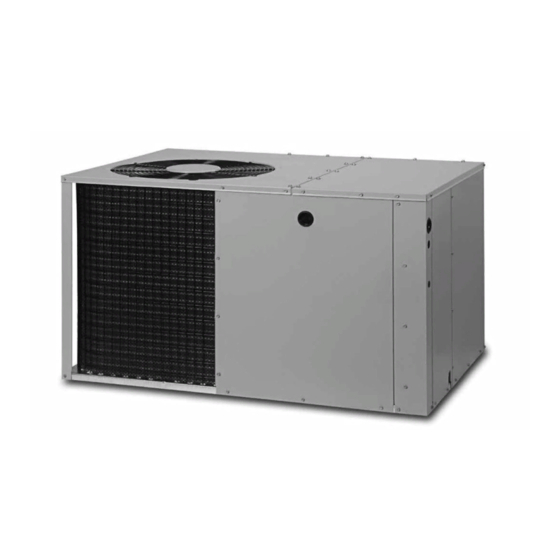
WSPM SERIES
14 SEER
INSTALLATION INSTRUCTIONS
PACKAGED AIR CONDITIONER - SINGLE STAGE, R-410A
IMPORTANT
ATTENTION INSTALLERS:
It is your responsibility to know this product better than your customer. This includes being
able to install the product according to strict safety guidelines and instructing the customer on
how to operate and maintain the equipment for the life of the product. Safety should always be
the deciding factor when installing this product and using common sense plays an important
role as well. Pay attention to all safety warnings and any other special notes highlighted in the
manual. Improper installation of the furnace or failure to follow safety warnings could result in
serious injury, death, or property damage.
These instructions are primarily intended to assist qualified individuals experienced in the
proper installation of this appliance. Some local codes require licensed installation/service
personnel for this type of equipment. Please read all instructions carefully before starting the
installation. Return these instructions to the customer's package for future reference.
DO NOT DESTROY. PLEASE READ CAREFULLY & KEEP IN A SAFE PLACE FOR FUTURE REFERENCE.
Advertisement
Table of Contents

Related Manuals for Rheem WSPM Series


Summary of Contents for Rheem WSPM Series
- Page 1 WSPM SERIES 14 SEER INSTALLATION INSTRUCTIONS PACKAGED AIR CONDITIONER - SINGLE STAGE, R-410A IMPORTANT ATTENTION INSTALLERS: It is your responsibility to know this product better than your customer. This includes being able to install the product according to strict safety guidelines and instructing the customer on how to operate and maintain the equipment for the life of the product.
-
Page 2: Table Of Contents
TABLE OF CONTENTS IMPORTANT SAFETY INFORMATION ............. 3 REQUIREMENTS & CODES ..............4 GENERAL INFORMATION ................ 4 Before You Install this Unit ..............4 Locating the Air Conditioner ..............4 Minimum Clearance Requirements ............4 Service Access Clearances ..............4 Clearances to Combustible Materials .......... -
Page 3: Important Safety Information
IMPORTANT SAFETY INFORMATION CAUTION: Please read all instructions before servicing this equipment. Pay attention to all safety warnings and any other special This unit uses R-410A refrigerant. DO NOT use notes highlighted in the manual. Safety markings are used any other refrigerant in this unit. Use of another frequently throughout this manual to designate a degree or level of seriousness and should not be ignored. -
Page 4: Requirements & Codes
REQUIREMENTS & CODES the air conditioner and its ducts in an area where they will be shaded from the afternoon sun, when the heat load is greatest. • All electrical wiring must be completed in accordance with • The length of the supply and return ducts should be kept to local, state &... -
Page 5: Air Conditioner Installation
SINGLE DUCT APPLICATION MULTIPLE DUCT APPLICATION Figure 2. Single & Multiple Duct Applications • Duct work should be attached directly to the unit flanges for D u c t horizontal applications. D im p le s T ra n s it io n •... -
Page 6: Locating & Installing The Supply Damper(S)
4. Insert the damper into the duct and bend over all tabs flat on the inside of the heat duct. 5. Seal the opening between the fiberboard and damper or flexible duct. Connecting the Return & Supply Air Flexible Ducts •... -
Page 7: Electrical Connections
ELECTRICAL CONNECTIONS WARNING: ELECTRICAL SHOCK, FIRE OR EXPLOSION HAZARD Failure to follow safety warnings exactly could result in serious injury, death or property damage. Improper servicing could result in dangerous operation, serious injury, death or property Strip Heat Voltage damage. High Voltage •... -
Page 8: Cooling Only Thermostat
CAUTION: 2 WIRE COOLING 4 WIRE HEAT/COOL THERMOSTAT (ONLY) THERMOSTAT Single Stage Electric Heat To avoid personal injury or property damage, YELLOW YELLOW make certain that the motor leads cannot come GREEN GREEN into contact with any metal components of the BROWN unit. - Page 9 RECOMMENDED MAXIMUM WIRE GAUGE WIRE LENGTH (FT) FROM UNIT TO THERMOSTAT Table 1. Control Wiring (24V) HEAT RISE DATA (BASED ON NOMINAL 10KW ELECTRIC HEAT KIT) EXTERNAL STATIC PRESSURE DROP - INCHES WATER COLUMN BLOWER UNIT SETTING HEAT HEAT HEAT HEAT HEAT HEAT...
-
Page 10: Air Circulation
3. Set the system mode to ON or COOL. 3. For the temperature measured, determine the required liquid 4. Set the temperature mode below room temperature. Verify refrigerant pressure from Table 4, (page 14), Table 5, (page that the indoor blower, outdoor fan, and compressor energize 14), Table 6, (page 15),... -
Page 11: Figures & Tables
FIGURES & TABLES Top View “A” “B” 3” 5.5” Opening for Opening for 12" Diameter 12" Diameter Supply Duct Return Duct 9.15” 1" 3.15” 9” 17.50” Rear View (1.5, 2, 2.5, & 3 Ton) 1.75” Ø Electric Heater Power Supply 1.13”... -
Page 12: Wiring Diagrams
Wiring Diagrams Figure 10. Wiring Diagram (1.5, 2, & 2.5 Ton Models) - Page 13 Figure 11. Wiring Diagram (3, 3.5, 4, & 5 Ton Models)
-
Page 14: Refrigerant Charging Tables
Refrigerant Charging Tables NOTES: LEGEND Shaded boxes indicate flooded conditions. 1. All pressures are listed psig and all temperatures in °F Rated design values. The suction pressure 2. Discharge temperatures greater than charted values indicate will vary from design value if outdoor air an undercharged system. - Page 15 OUTDOOR TEMPERATURE (° F) SUCT. PRESS. LIQ. DIS. LIQ. DIS. LIQ. DIS. LIQ. DIS. LIQ. DIS. LIQ. DIS. LIQ. DIS. LIQ. DIS. PRESS. TEMP. PRESS. TEMP. PRESS. TEMP. PRESS. TEMP. PRESS. TEMP. PRESS. TEMP. PRESS. TEMP. PRESS. TEMP. Table 6. Charging Table for 2.5 Ton Units (030J Model) OUTDOOR TEMPERATURE (°...
- Page 16 OUTDOOR TEMPERATURE (° F) SUCT. PRESS. LIQ. DIS. LIQ. DIS. LIQ. DIS. LIQ. DIS. LIQ. DIS. LIQ. DIS. LIQ. DIS. LIQ. DIS. PRESS. TEMP. PRESS. TEMP. PRESS. TEMP. PRESS. TEMP. PRESS. TEMP. PRESS. TEMP. PRESS. TEMP. PRESS. TEMP. Table 8. Charging Table for 3.5 Ton Units (042J Model) INDOOR WET-BULB TEMPERATURE (°F) 26.6...
- Page 17 Remove refrigerant when above curve Add refrigerant when below curve Liquid Temperature ( ° F ) Figure 12. Charging Chart for 5 Ton Units (X60J Model)
-
Page 20: Installation Checklist
INSTALLATION CHECKLIST REFRIGERATION SYSTEM INSTALLATION ADDRESS: Was unit given 24 hr warm up period for crankcase heaters (if equipped)? CITY _________________________________________ STATE _____________________________ Stage-1 Liquid Pressure (high side) _______________________________________________________ Stage-1 Suction Pressure (low side) _______________________________________________________ UNIT MODEL # _______________________________________________________________________ ELECTRICAL SYSTEM UNIT SERIAL # _______________________________________________________________________ Unit Installed Minimum clearances per Electrical connections tight?
Need help?
Do you have a question about the WSPM Series and is the answer not in the manual?
Questions and answers