
Related Manuals for WHISPER KOOL Platinum Split 4000

Summary of Contents for WHISPER KOOL Platinum Split 4000
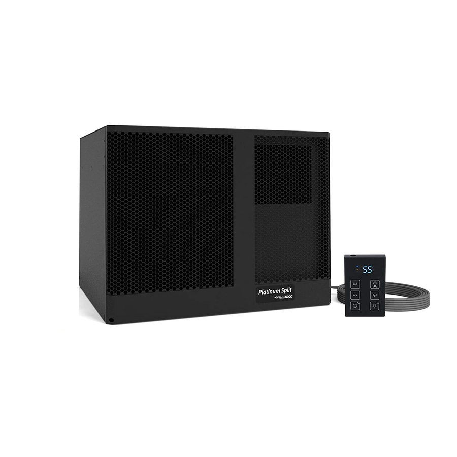
- Page 1 COLD WEATHER START KIT Platinum Split 4000 Cold Weather Start Kit: To be used in conjunction with Platinum Split 4000 (Manufactured After 01/07/15) cooling system. The Coolest Thing In Wine Storage 051515 LASS.PS.4A...
- Page 2 Conforms to ANSI/UL Std 427 Certified to CAN/CSA Std C22.2 No. 120 We manufacture, test and certify 100% of our wine cooling units in the USA. By sourcing the best components and closely controlling our manufacturing processes, we can assure the highest-quality, lowest defect manufacturing rates in the industry.
-
Page 3: Table Of Contents
TABLE OF CONTENTS Receiving & Inspecting the System ......3 Before You Start ..........4 Condensing Unit Cold Weather Start Kit Installation Instructions . - Page 4 This Owner’s Manual is intended to provide detailed instructions for the installation of the Cold Weather Start Kit to the Platinum Split 4000 cooling system. In order to ensure the proper longevity of your cooling unit, the equipment should be installed as outlined in this Owner’s Manual. It is also vital to establish a proper care and maintenance schedule.
-
Page 5: Receiving & Inspecting The System
RECEIVING & INSPECTING THE SYSTEM Receiving and Inspecting the System • Inspect the packaging for any obvious signs of damage or mishandling before opening the container. • Note any discrepancies or visual damage on the Bill of Lading before signing. Review the Packing Slip to Verify Contents •... -
Page 6: Before You Start
BEFORE YOU START Shut Off Power going to the Evaporator and Condensing Unit. Disconnect both the evaporator unit (Air Handler) and the Condensing Unit from each power source. WARNING: Failure to do so may cause electrical shock which can result in injury or death. A 2 wire 18-20 awg thermostat wire will need to be ran from the evaporator unit to the condensing unit prior to installing the Cold Weather Start Kit. -
Page 7: Installation Instructions
CONDENSING UNIT COLD WEATHER START KIT INSTALLATION INSTRUCTIONS Remove the electrical box cover. Remove the sticker backing from the paper jig and stick to the side of the existing electrical box as shown. (The cross should be slightly offset to the right.) Using a step bit, drill a 5/8”... - Page 8 Remove the backing on the double sided tape as shown. Remove the backing on the double sided tape as shown. Line up the back of both boxes and stick the Cold Weather Start Kit box the condensing unit and existing electrical box. Cut the 3 zip ties around the hot and neutral wires off as shown.
- Page 9 Reorganize wires in H lever connector as shown. Reorganize wires in N lever connector as shown. Secure the #6 wire into the H2 lever connector. Secure the #7 wire into the H2 lever connector. www.whisperkool.com | Page 7...
- Page 10 Secure the #5 wire into the N lever connector. Secure the #8 wire into the H lever connector. Remove the blue flag connector from the #1 terminal on the Delay on Break Timer. Cut the blue flag terminal off the black wire from the previous step.
- Page 11 Strip the end of the black wire from the previous step to a length of 3/8”. Crimp the yellow female disconnect labeled 1 onto the #11 wire and the black wire from the previous step. Connect the yellow female disconnect labeled 1 to the #1 terminal on the Delay on Break Timer.
- Page 12 Cut the yellow female disconnect off of the two wires from the previous step. Strip the ends of each of the two wires from the previous step to a length of 3/8”. Crimp the red female disconnect labeled 3 onto the black wire from the previous step.
- Page 13 Twist the strands of the blue wire from 3 steps ago with the #10 wire. Crimp the closed end terminal onto the #10 wire and the blue wire from the previous step. Locate the silicone heater assembly. Loosen the two screws on the cord squeeze on the existing electrical box.
- Page 14 Route the two long white wires from the silicone heaters up into the electrical box. Twist the strands of each heater wire together. Secure the two heater wires into the N Lever connector. Route the #9 wire with the red disconnect labeled T down through the cord squeeze.
- Page 15 Remove the backing from one silicone heater. Stick the silicone heater to the receiver as shown. Line up silicone heater wires with the stud on the back of the fan motor. The top of the heater should be 2.5” from the top of the receiver. 2.5”...
- Page 16 Secure 2 hose clamps around the top and bottom of the silicone heaters as shown. Slide the thermal switch assembly over the top of the receiver as shown. Secure the blue female disconnect labeled T onto the bottom terminal of the thermal switch. Secure the red female disconnect labeled T onto the top terminal of the thermal switch.
- Page 17 Zip tie thermal switch and heater wires as shown. (5x) Zip tie wires in locations shown. Route the 24v thermostat wires through the cord squeeze into the electrical box. Remove the 4 Phillips head screws on the Cold Weather Start Kit Electrical Box. www.whisperkool.com | Page 15...
- Page 18 Remove the top cover from the on Cold Weather Start Kit Electrical Box. Route the 24v thermostat wire through the hole in the boxes into the Cold Weather Start Kit Electrical Box. Connect one of the 24v thermostat wires to the #13 wire using the wire nut provided.
- Page 19 Tuck wires in Cold Weather Start Kit Electrical box as shown. Using the 2 provided ½” self taping screws, secure the 24V coil relay to the Cold Weather Start Kit box through the predrilled holes. (Failing to use the provided screws and mounting locations may result in a punctured coil.) Tuck wires in electrical box as shown.
- Page 20 Make sure that the Delay On Break relay is set to 5 minutes. Secure the 2 screws on the cord squeeze. Secure both tops back onto the electrical boxes using the removed screws. Cut the corner of the bag off as shown. 051515 LASS.PS.4A Page 18 | 1-800-343-9463...
- Page 21 Place thermal paste on the flat surface of the thermal switch. Be sure the thermal switch is making good contact with the receiver under the ridge. The Cold Weather Start Kit has been successfully installed on the condensing unit, next proceed to the evaporator unit instructions. www.whisperkool.com | Page 19...
- Page 22 NOTES 051515 LASS.PS.4A Page 20 | 1-800-343-9463...
-
Page 23: Evaporator Unit Cold Weather Start Kit
EVAPORATOR UNIT COLD WEATHER START KIT INSTALLATION INSTRUCTIONS Before beginning the installation process, locate the Evaporator Unit Cold Weather Start Kit. All parts for the Evaporator Unit are located inside of this box. Open box and remove the 24v transformer and the zip lock bag. - Page 24 Wall Mounted Units Pull front panel away from the unit to remove it. Set panel aside. Ducted Units Using a Phillips Head Screw driver loosen the 4 screws on the ducting panel, make sure screw comes all the way out of the housing of the unit. (Note: The screws do not come out of the panel.) Pull ducting panel away from the unit to remove it.
- Page 25 Pull electrical panel out and let hang as shown. Remove the backing from the double sided tape on the bottom and side edges of the transformer. Place flange of the transformer between the control box and the flange of the electrical panel, place the other flange underneath the grommet.
- Page 26 Secure the two white wires from the unit and the white wire from the transformer into a lever connector. Locate the blue wire coming out of the Molex connector. Cut the blue wire and strip each end to a length of 3/8”. Secure the blue wires from the unit and the black wire from the transformer into a lever connector.
- Page 27 Secure the other t-stat wire and the yellow wire coming from the 24v side of the transformer into a lever connector. Zip tie wires in locations shown. Slide the electrical panel back into place and re-install the thumb screw. Wall Mounted Units Secure one of the t-stat wires and the blue wire coming from the 24v side of the transformer into a lever connector.
- Page 28 Ducted Units Push ducting panel back on unit and tighten the 4 screws on the ducting panel to the unit. The Cold Weather Start Kit has been successfully installed on the Evaporator Unit. If the installation process is complete on the condensing unit as well, plug both the condensing unit and evaporator units back into a power source.
- Page 29 NOTES 051515 LASS.PS.4A...
- Page 30 WhisperKOOL 1738 E. Alpine Ave Stockton, CA 95205 1-800-343-9463 www.whisperkool.com 051515 LASS.PS.4A...
Need help?
Do you have a question about the Platinum Split 4000 and is the answer not in the manual?
Questions and answers