Sign In
Upload
Download
Add to my manuals
Delete from my manuals
Share
URL of this page:
HTML Link:
Bookmark this page
Add
Manual will be automatically added to "My Manuals"
Print this page
×
Bookmark added
×
Added to my manuals
Manuals
Brands
Vox Manuals
Musical Instrument
V301H
Troubleshooting manual
Vox V301H Troubleshooting Manual
Combo-organ
Hide thumbs
1
2
3
4
5
6
7
8
9
10
11
12
13
14
15
16
17
18
19
20
21
22
23
24
page
of
24
Go
/
24
Bookmarks
Advertisement
Quick Links
Download this manual
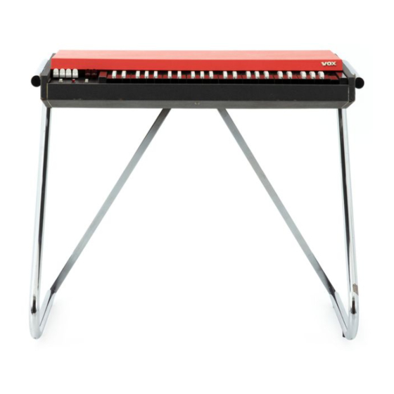
TROUBLE-SHOOTING
COMBO-ORGANS
Vox Continental models
V301H, 301J, 303J
1
Previous
Page
Next
Page
1
2
3
4
5
Advertisement
Need help?
Do you have a question about the V301H and is the answer not in the manual?
Ask a question
Questions and answers
Related Manuals for Vox V301H
Musical Instrument Vox Giulietta VGA-3D Owner's Manual
Archtop acoustic electric guitars (32 pages)
Musical Instrument Vox Giulietta VGA-3PS Owner's Manual
Archtop acoustic electric guitar (29 pages)
Musical Instrument Vox Giulietta VGA-5TPS Owner's Manual
Archtop acoustic electric guitars (29 pages)
Musical Instrument Vox V301J Troubleshooting Manual
Combo-organ (24 pages)
Musical Instrument Vox VUP-33-SOW Owner's Manual
Ukulele (2 pages)
Musical Instrument Vox Bobcat S66 Owner's Manual
Semi-hollow electric guitars (16 pages)
Musical Instrument Vox Starstream Series Owner's Manual
(16 pages)
Musical Instrument Vox APC-1 Owner's Manual
(48 pages)
Musical Instrument Vox Continental Organ Owner's Manual
(8 pages)
Musical Instrument Vox SDC-1 mini Owner's Manual
(16 pages)
Musical Instrument Vox Electric Ukulele Owner's Manual
(4 pages)
Musical Instrument Vox CONTINENTAL TYPE 1 HARMONICA KEY OF A Instructions Manual
10-hole diatonic (6 pages)
This manual is also suitable for:
V301j
V303j
Print
Rename the bookmark
Delete bookmark?
Delete from my manuals?
Login
Sign In
OR
Sign in with Facebook
Sign in with Google
Upload manual
Upload from disk
Upload from URL


Need help?
Do you have a question about the V301H and is the answer not in the manual?
Questions and answers