Table of Contents
Advertisement
Quick Links
DESIGNED
TO FIT:
MODEL YEAR:
2016-NEWER
COLLECTION SYSTEM
MODEL #
ALTERNATE
MODEL #
OF ADDED WEIGHT KIT P# 59B30037150 (A1149) FOR SAFE OPERATION!
OF ADDED WEIGHT KIT P# 59B30037150 (A1149) FOR SAFE OPERATION!
MANUAL PART#: Q0507
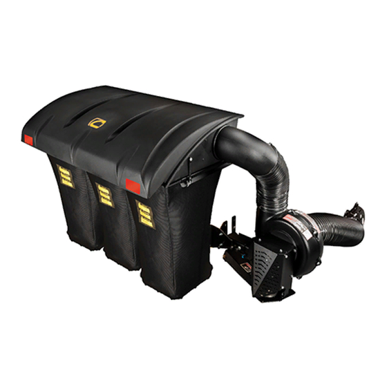
POWER ASSIST TRIPLE BAG
PRO Z 500, 700, 900 L&S
59A30047150
21131509
*L MODELS:
*L MODELS:
COLLECTION SYSTEM REQUIRES INSTALLATION
COLLECTION SYSTEM REQUIRES INSTALLATION
OPERATOR'S MANUAL
ASSEMBLY
Series:
54" & 60" DECKS
OPERATION
MAINTENANCE
PRO-X
Rev 3.1 - Oct 2020
Advertisement
Table of Contents

Related Manuals for Cub Cadet 59A30047150


Summary of Contents for Cub Cadet 59A30047150
- Page 1 POWER ASSIST TRIPLE BAG TO FIT: MODEL YEAR: Series: 2016-NEWER PRO Z 500, 700, 900 L&S 54” & 60” DECKS COLLECTION SYSTEM 59A30047150 MODEL # ALTERNATE 21131509 MODEL # *L MODELS: *L MODELS: COLLECTION SYSTEM REQUIRES INSTALLATION COLLECTION SYSTEM REQUIRES INSTALLATION...
-
Page 2: Table Of Contents
GRASS COLLECTION SYSTEM TABLE OF CONTENTS SECTION PAGE SECTION PAGE Safety - - - - - - - - - - - - - - - - - - - - - - - - - - - - - - 2 2-14 Lower Hose To Blower Cone Installation- - - - - - 13 Safety Alert Symbols - - - - - - - - - - - - - - - - - - - - - - 3 2-15 Lower Hose To Boot Installation - - - - - - - - - - - 13... -
Page 3: Safety Alert Symbols
SAFETY WARNING! NEVER operate the mower unless the discharge guard and either the deflector assembly or the vacuum collector adapter are fastened securely in place. WARNING! Do not work around the mower deck boot or the blower area until you are certain that the mower blades and the blower impeller have stopped rotating. -
Page 4: Warranty
PECO LIMITED WARRANTY FOR NEW PRODUCTS New PECO, Inc. extends the following warranties to the ORIGINAL PURCHASER of each New PECO, Inc. consumer product purchased from one of our Dealers or directly from New PECO, Inc., subject to the following limitations: A. -
Page 5: Iintroduction And Description
Section I - INTRODUCTION & 2-1 Preparation Of Mower From the underside of the engine, disconnect the wiring DESCRIPTION harness attached to the electric clutch. Remove the bolt and electric clutch from the mower. Refer to Figure 2-1a. 1-1 Introduction Remove the D-drive spacer using an arbor press or Your grass collection system has been designed to give equivalent. -
Page 6: Mount Arm Preparation And Installation
2-2 Mount Arm Preparation and Installation Remove the (4) 3/8”-16 x 1-1/4” existing Carriage Bolts and (4) 3/8”-16 Ny-Flange Lock Nuts from the right-rear of the mower and discard. Refer to Figure 2-2a. First, loosely attach the Mount Arm Brace P#(B0953) to the Mount Arm Assy. P#(A2071) using (2) 3/8”-16 x 1” Carriage Bolts P#(K1182) and (2) 3/8”-16 Ny-Flange Lock Nuts P#(K2038). -
Page 7: Pto Drive Assembly
2-3 PTO Drive Assembly Once the Mount Arm Assembly P#(A2071) is installed and secured to the mower, assemble the Drive Assembly P#(A2072), Belt Guard Assembly P#(A2069_03), Idler Mount Assembly P#(A2067_03) & Belt Guard Gusset P#(B1026). First, attach the Belt Guard Assembly P#(A2069_03) to the Drive Assembly P#(A2072) using (2) 1/4”-20 x 5/8” Carriage Bolts P#(K1010) and (2) 1/4”-20 Ny-Flange Lock Nuts P#(K2014). - Page 8 2-3 PTO Drive Assembly (Continued) Attach the Idler Mount Assembly P#(A2067_03) to the Drive Assembly using (1) 3/8”-16 x 1” HHCS (A) P#(K1191), (1) 3/8”-16 x 1” Carriage Bolt (B) P#(K1182) and (2) 3/8”-16 Ny-Flange Lock Nuts P#(K2038). Refer to Figure 2-3b. Leave Bolts Loose (Note: Orientation of bolts A &...
-
Page 9: Drive Assembly And Belt Installation
2-4 Drive Assembly and Belt Installation (Note: It is recommended that someone assist during this step.) Insert the Drive Assembly into the receiver tube on the Mount Arm Assembly until the Knob Plunger Pin engages. Once in place, turn Lock Handle clockwise until tight. Next, feed the AK83 Belt P#(M0315) between the Belt Guard and the Idler Mount Assembly. -
Page 10: Lower Mount Tube Installation
2-5 Lower Mount Tube Installation Figure 2-7 Secure the (2) Lower Mount Tubes P#(B0752) to the Clevis rear frame using (2) 5/16”-18 U-bolts P#(K1098) and (4) 5/16”-18 Ny-Flange Lock Nuts P#(K2516) PER TUBE. Hair Pin Nylon Refer to Figure 2-5. Note: Bottom of Tubes should rest Clip Flange on the top edge of the Trailer Hitch Plate. -
Page 11: Blower Cone Installation
2-10 Blower Cone Installation Thread (1) 5/16”-18 jam nut P#(K0120) onto each end of (2) 5/16”-18 x 2-1/2” HHCS P#(K0125) as shown in Figure 2-10a. Figure 2-10a Thread (1) Jam Nut Onto Each 5/16”-18 Bolt Now partially thread (1) bolt into each of the two threaded bosses located on the blower housing. Place 8” Blower Cone P#(E6009) so the two tabs line up with the bolts and tighten completely as shown in Figure 2-10b. -
Page 12: Boot To Mower Deck Installation
According to deck size, align marked holes and Boot 2-11 Boot To Mower Deck Installation holes. Secure the Boot Mounting Assembly P#(A2045) to the Aluminum Boot P#(E0028A) using (2) 3/8”-16 x 1” NOTE: The Boot Kit Assembly is designed to fit the 54” Carriage Bolts P#(K1182) and (2) 3/8”-16 Ny-Flange and 60”... -
Page 13: Length Of Hose Adjustment
2-12 Length Of Hose Adjustment 2-14 Lower Hose To Blower Cone Installation The hoses in the following steps must be cut to fit your machine. Do not cut the hoses until you have tried to fit Slide a pre-assembled Hose Clamp P#(J0080) over both them on your machine. -
Page 14: Installation/Removal Of Collection Bags
2-16 Installation/Removal Of Figure 16-c Collection Bags Plastic Top IMPORTANT! To prevent bag wear, install (1) black rubber end cap P#(F0010), as shown in Figure 2-16a, on each bag ring after rotating bag 360°. Bag Ring Figure 2-16a Black Rubber Connector Fasten Draw- Latch Here &... -
Page 15: Safety Interlock Harness Installation
Route the Drive Clutch Connector (D) around the front 2-17 Safety Interlock Harness side of the engine, between the ROPS and gas tank and Installation through the opening in the rear bumper connecting to the quick connect plug located on the PTO Drive. Collection System May Require Dealer Installation! Before installing, please verify the presence of an Before routing the PTO Switch (E), locate and remove... - Page 16 2-17 Safety Interlock Wiring Harness Installation (Continued) Figure 2-17b Retainer Plate Drive Bagger Clutch PTO Switch Connector 5-Way Male Main Harness Connector Engine Connector Engine Side Engine Connector...
-
Page 17: Safety Interlock Harness Wiring Schematic
2-17 Safety Interlock Harness Installation (Continued) Wiring Schematic P0274 Rev. 1... -
Page 18: Impeller Blade Removal/Replacement
2-18 Impeller Blade Removal/Replacement To Remove: First remove the 5/16”-24 x 1-1/2” HHCS GR8 P#(K1465) (#1), Taper-Lock Bushing Washer P#(K0284) (#3) and (2) Spacer Bushings P#(S0159) (#4) from the Taper-Lock Bushing P#(S0157) (#5). See Figure 2-18. Next remove the (2) 1/4”-20 x 1” HHCS (#2) and place them into the threaded holes of the Taper-Lock Bushing (#5). Gradually thread each bolt evenly into the Taper-Lock Bushing, forcing the Impeller Blade to break-away from the Taper-Lock Bushing. -
Page 19: Even Bag Fill Adjustment
2-19 Even Bag Fill Adjustment Flap Can Be Adjusted Up/Down Depending On Mowing Conditions. Adjust Flap Up To Allow More Dense Material To Reach Left Bag. Adjust Flap Down To Allow Less Dense Material To Reach The Right Bag. Once Adjusted Properly, All Bags Should Fill Evenly, But May Require Further Adjusting When Mowing Conditions Change. -
Page 20: Weight Kit Installation Instructions
Weight Kit Installation Instructions Weight Kit Installation Instructions Figure 1-3 Cub Cadet Tank LZ & L Models - Installing a weight kit is mandatory for safe operation of the collection system. SZ & S Models do not require a weight kit. -
Page 21: Exploded Views & Parts List
A2071 Mount Arm Assembly Item # Part # Desc. Qty. A2040 Mount Arm Sub-Assy J0009 Adjustable Handle 1/2"-13 x .59 Male J0013 Nylon Flat Washer 1/2" x .750" OD Grade 6/6 J0020 Knob Plunger Pin 1/2"-13 K0027 Flat Washer 1/2" / .787 OD x .512 ID x .090 T... - Page 22 A2045 Boot Mounting Assembly Item # Part # Desc. Qty. A2044 Deck Plate Assy A2043 Boot Plate Assy K1429 3/8"-16 x 6" HHCS GR5 K0042 Flat Washer 5/16" / .875 OD x .380 ID x .075 T K2038 Ny-Flange Lock Nut 3/8"-16 J0017_1 Torsion Spring K1146...
- Page 23 A2092 Idler Arm Assembly Item # Part # Desc. Qty. A2070_01 Idler Arm Weldment K1467 Flat Washer M6 x 12mm OD J0801 1/4"-28 Zirc Fitting A2067_03 Idler Mount Assembly Item # Part # Desc. Qty. B0958_03 Idler Mnt Pl K2038 Ny-Flange Lock Nut 3/8"-16 K1463 Flat Washer .720 ID x 1.500 OD x .250 T...
- Page 24 A2058 Gearbox Sub-Assembly...
- Page 25 A2059_01 Clutch Sub-Assembly A2059_01 Clutch Sub-Assembly...
- Page 26 A2057_01 Drive Assembly Exploded Parts View...
- Page 27 A2060_01 Mounted Drive Assembly...
- Page 28 A2039_02 Base Drive Assembly...
- Page 29 A2072_01 Drive Assembly / 5 Blade Impeller...
- Page 30 1/4"-20 Nyloc Nut C0026 Grass Deflector K0062 3/16" x 1-1/2" Fender Washer, Z K1265 Black Panel Retainer V1120 Black Plastic Screen V1118 DUST GUARD R1057 2" x 4" Red Reflector Label R1065 Made In America Decal R0023 Decal / Cub Cadet 'C'...
-
Page 32: Safety Decals
To promote safe operation, New PECO, Inc. supplies safety decals on all products manufactured. Damage can occur to safety decals either through shipment, use or reconditioning. Contact your local Service Center for replacement decals. Part# R0023 Part# R0022 Cub Cadet Designed & Built Logo In The USA... -
Page 33: Operating Instructions
SECTION III OPERATING INSTRUCTIONS General Safety Disengagement Of The PTO Assembly Only qualified people familiar with this operator’s manual A. To disengage the PTO assembly, move Bagger PTO and the mower’s operator’s manual should operate this switch to the off position. machine. -
Page 34: Lubrication
New PECO, Inc. and include the following information on the chart below. WRITE THE MODEL AND 59A30047150 THE SERIAL NUMBER PLATE SERIAL NUMBER IN THE IS LOCATED ON THE TOP... -
Page 36: Troubleshooting
Troubleshooting Collection System Performance Problem Possible Cause Corrective Action — Cutting blades are bent or — Install new cutting blade unbalanced — Loose blower pulley or pulley Abnormal Vibration — Tighten the pulley assembly — Contact dealer to replace — Impeller blade out of balance —... -
Page 37: Notes
Notes... - Page 38 Cub Cadet LLC P.O. Box 361131 Cleveland, Ohio 44136-0019 Phone: 1-877-282-8684 MTD Products Limited Kitchener, ON N2G 4J1 1-800-668-1238...
Need help?
Do you have a question about the 59A30047150 and is the answer not in the manual?
Questions and answers