
Related Manuals for FujiClean CE Series

Summary of Contents for FujiClean CE Series
- Page 1 ENGINEER PACKAGE Intelligently Engineered Onsite Wastewater Treatment Systems Distributed By Cell: 631-405-0358 Website: www.awsli.com Email: bryan@awsli.com...
- Page 2 Reasons for Using Fuji Clean Treatment Systems in Suffolk County Worldwide Leader in Onsite Treatment Systems Over 2 Million Systems Installed Worldwide Smallest Footprint Category 1 System: Allows for Best Reduction in PSD sizing No Interior Moving Parts (no pumps, agitators, emitters, etc.) ...
-
Page 3: Table Of Contents
Designer and Engineer Manual Residential and Commercial Systems Sections 1. Installation Overview………………………………………………………………….…… Page 2 2. Treatment Process Overview……………………………………………………….…… Page 3 3. System Components and Specifications a. Summary ………………………………………………………………..…………… Page 4 b. FujiMACRII Blowers …………………………………………………………….. Page 5 c. Alarm Panel (incl. wiring diagra s for A & C pa els ……... Page 7 d. -
Page 4: Installation Overview
Installation Overview System Controller/Alarm (supplied by Fuji Clean USA) Suffolk County requires FujiMACRII series blower power connection to be hardwired to control panel. System vents through house vent system. For houses with house traps For connection of SJE Rhombus Signalmaster float switch cord to alarm panel, installed, vent system drill hole in riser and use male fitting and electrical conduit. -
Page 5: Treatment Process Overview
Section 2. Treatment Process Overview Fuji Clea ’s o ta t filtratio treat e t is a si ple, ell e gi eered pro ess that o sists of a o trolled, ir uitous flow train through anaerobic and aerobic chambers and in direct contact with assorted proprietary fixed film medias on which biological digestion of organic matter occurs. - Page 6 Section 3a. System Components and Specifications – CEN Summary FUJI CLEAN USA CEN Series CEN SYSTEM BOD, TSS, Enhanced TN SPECIFICATION TABLE Model CEN5 CEN7 CEN10 CEN21 Load Hydraulic* (GPD) 1,900 Effluent** (assumes domestic strength influent) BOD (mg/L) TSS (mg/L) TN (mg/L) FujiMAC80RII FujiMAC100RII...
-
Page 7: Fujimacrii Blowers
Section 3b. System Components – FujiMACRII Blowers The Table below includes specifications for FujiMACRII series blowers. The table below includes blower models associated with each standard system installation. Some installations may require upsized blowers based on overall distance (i.e. air conduit length and diameter) and number of elbows from blower to treatment system. - Page 9 Section 3c. System Components - Alarm / Control Panel NEMA 4X rated, the Alarm/Control Panel monitors tank water level and blower operation. An audible horn and red beacon light will activate in the event of either a tank high water condition or if the blower ceases to operate (causing a drop in air pressure).
- Page 10 Fuji Clean USA Co troller A Circuit Alarm Circuit Breaker Breaker Float Switch, Pressure Switch, Test/Normal/ Air Blower Test/Normal/Silence Switch Silence Switch Circuit Breaker (Extra component if Alarm Beacon necessary, such as discharge pump) Pressure Switch Terminal Blocks Blower Hardwire Line Wiring Diagram Horn...
- Page 11 Co troller A Wiri g Diagram...
- Page 12 Co troller C Wiri g Diagram...
- Page 13 Section 3d. System Components – Wi-Fi Communications Device The SJE Rhombus MySpy Wi-Fi Messenger requires controller communication contacts. Fuji Clean USA Co troller C is the ost asi o troller odel that pro ides these o ta ts. This de i e ust e mounted within range of home Wi-Fi signal.
- Page 15 Section 4. Maintenance Program Scheduled Maintenance – General If sampling is required, please draw samples prior to maintenance protocol. Refer to Appendix 3 for proper sampling procedure. Regularly scheduled maintenance by a qualified service professional is necessary for efficient operation of this system. Recommended frequency of scheduled maintenance; semi-annually (about 20-30 minutes to complete per visit).
- Page 16 Blower Air Filter Cleaning / Replacement Procedure Replacing the blower air filter is very simple and consists of removing the filter cover with a Phillips screwdriver, removing the old, cleaning it (blow clean with air pressure) or replacing it with a new filter, and then screwing the cover back into place.
- Page 17 Take samples from either Open all access covers and secure the area around the “torage Cha er or Disi fe tio Cha u less access openings. chlorine is used). 5. Treated Effluent Check. (Recommended frequency: 1x every 6 months) Collect a sample of treated effluent from the aeration chamber and evaluate for clarity and odor and pH.
- Page 18 At start-up, and for standard operation, the 9. Set Recirculation Model Default Setting Recirculation Control Valve (gray) should be set Control Valve. (gray) according to the table and instructions listed (Recommended under Procedure #9. NOTE: CEN systems have a 30% to 35% higher recirculation rate than CE systems.
- Page 19 12. Backwash and Sludge Step 3. Reset the Recirculation Step 8. Flush the Effluent Transfer. (Recommended Control Valve (grey valve) to the Control Valve (white) by frequency: 1x every 6 months) original position. rotating the valve back and Perform a backwash and sludge forth from 0 to 100 several transfer operation.
- Page 20 13. Check / Clean Effluent Airlift 15. Refill the chlorinator (if applicable). Place Pipe. (Recommended frequency: refill chlorination tablets in the chlorinator Start-up and 1x every 6 months) tube and adjust the dissolve rate by rotating Check the observation port in the the bottom cap of the chlorinator.
- Page 21 17. Measure Sludge and Pump Out if Necessary (Recommended frequency: 1x every 2 years or as required) • Biological treatment performance is severely deteriorated due to excessive amounts of oil or chemicals which interfere with the bacterial activity. • For residential models, when sludge levels reach more than 35-inches in Chamber 1 or more than 16-inches in Chamber 2.
-
Page 23: Alarm Panel
Thank you for choosing to install a Fuji Clean USA treatment system. We care that the system is installed properly and thoughtfully. Fuji Clean USA or your qualified distributor will train and certify you for proper installation. PLEASE contact your distributor or Fuji Clean USA for assistance or with ANY questions. - Page 24 Contractor Installation Manual – Residential Systems Equipment Supplied by Contractor Risers and Covers per Site & Regulatory Requirements Note: Tuf-Tite and Polylok Risers in 6” or ” height increments and covers are available from your distributor . If not already installed, please refer to page 5 for installation instructions. Allowed 4”...
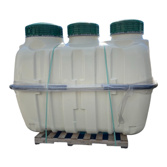
- Page 25 Installation Procedure Unloading Instructions: Upon delivery, inspect Fuji Clean tank, both outside and inside for possible damage incurred during transport. If you find damage, or have a question, please contact your distributor immediately. Step 1: Prepare excavation to be at least 1 to 2 feet ...
- Page 26 Step 4: If any part of the tank is below the estimated seasonal high water table, then engineer shall provide buoyancy calculations to assure adequate tank uplift restraint. Recommended uplift restraint options include: Uplift Restraint with Tie-Down Straps Do NOT use Lifting Lugs for uplift restraint.
- Page 27 Step 5: After rechecking that tank is level to 1/8-inch, (fore and aft as well as side to side), fill tank with fresh water to the low water line mark. Note: Alternate chambers while filling for evenly balanced fill. Low water line in sedimentation chamber Please note: To assure tank water tightness, please check in 24 hours to be sure that the water level has not dropped.
- Page 28 “tep : Usi g supplied adaptors a d fitti gs, atta h air pipe fitti g to ta k a d o e t to ¾ o duit i prepared tre h deep to lo atio of air lo er. Please ote: ¾ fle i le irrigation line, 100 PSI Max, may also be used for the airline.
- Page 29 Plan view shows trench excavations for inlet and outlet lines Note: Some states and installing contractors require hard wired blower connection Step 8 continued: Locating and Installing Blower/Control Panel cont. Alarm Panel shall be: in a well ventilated area as dry and protected from elements as possible ...
- Page 30 Step 9: For cold climate installations, please install insulated risers and covers and cover upper half of treatment unit with min. R-8 value insulating material (i.e. foam board) For connection of float switch cord to alarm panel, drill hole in riser and use male fitting and electrical conduit.
- Page 31 Step 12: In nearly all cases, the Fuji Clean system will vent properly through the house septic influent line. In cases where there is a influent pump, or in severe downdraft locations, a separate vent should be considered. If you do choose to install a vent, be sure that the vent slopes toward the tank so that any moisture accumulation drips back down toward the tank.
-
Page 32: Start-Up Procedure
Start-Up Procedures □ 1. Outside Environment Check. The system is accessible and nothing inhibits access to maintenance. • Surface water is draining away from risers and covers. • No signs of physical damage to the treatment system, piping, alarms or components •... - Page 33 □ 7. Check Recirculation Flow Rate. • Normal recirculation flow should be level with the top edge of the airlift pumpback line cut-out spilling into Chamber 1, the Sedimentation Chamber. □ 8. Check/Set Aeration Balance Control Valve (blue). • The default, normal setting for the Aeration Control Valve is 50%.
- Page 34 □ 11. Add Disinfectant Tablets to Chlorinator (if appropriate) • If chlorine tablets are to be used for disinfection, check to be sure that they are removed from packaging and placed in the disinfectant cylinder. • Be sure that disinfectant cylinder remains closed for all start-up steps to prevent corrosive activity to exposed metallic surfaces.
- Page 35 Fuji Clean USA Installation Procedure Checklist Note: Please consult Installation Manual for detailed instructions. Unloading Instructions: Upon delivery, inspect Fuji Clean tank, both outside and inside for possible damage incurred during transport. If you find damage, or have a question, please contact your distributor immediately. ...
- Page 36 Fuji Clean USA Installation Procedure Checklist cont. Alarm Panel shall be: in a well ventilated area as dry and protected from elements as possible in as close of proximity to the FujiMAC blower as possible wired by qualified electrician ...
- Page 41 PAGE 1 OF 7 PAGES ...
- Page 42 PAGE 2 OF 7 PAGES ...
- Page 43 ENGINEERING DRAWINGS AND DETAILS PAGE 3 OF 7 PAGES 2-1/2" VENTILATION PIPE 2-1/2" VENTILATION PIPE CHAMBER Volume (gal) CHAMBER Volume (gal) SCUM BAFFLE SCUM BAFFLE Sedimentation Chamber 8'-2 3 " Sedimentation Chamber CHAMBER Volume (gal) 7'-10 4 " Anaerobic Filtration Chamber 2'-11 8 "...
- Page 44 ENGINEERING DRAWINGS AND DETAILS PAGE 5 OF 7 PAGES COMPACTED SELECT FILL TO GROUND SURFACE FUJI CLEAN CE- OR CEN-SERIES UNIT SLOPE GRADE TO SHED WATER FROM TANK LIDS. POUR CONCRETE COLLAR AROUND TANK. TANK RESTRAINT PLATE PROVIDE CONCRETE ACCORDING TO MODEL. (ALREADY INSTALLED) PLACE CONCRETE EQUALLY AROUND TANK.
- Page 45 ENGINEERING DRAWINGS AND DETAILS PAGE 6 OF 7 PAGES 6" MIN. TOPSOIL GRADE TO SHED FROM TRENCH NATIVE BACKFILL INFILTRATOR QUICK4 PLUS LOW PROFILE 6" MIN. 8" 34" UNIT DISPERSAL LATERAL iTYP.) 36" TRENCH 24" GRAVITY DISPERSAL SECTION VALVE BOX WITH LID 1"...
- Page 46 PAGE 7 OF 7 PAGES...
- Page 47 Intelligently Engineered Onsite Wastewater Treatment Systems Distributed By Cell: 631-405-0358 Website: www.awsli.com Email: bryan@awsli.com...
Need help?
Do you have a question about the CE Series and is the answer not in the manual?
Questions and answers