Table of Contents
Advertisement
Quick Links
Advertisement
Table of Contents

Subscribe to Our Youtube Channel
Related Manuals for Vascat MAC R Series


Summary of Contents for Vascat MAC R Series
- Page 1 INSTRUCTIONS AND MAINTENANCE MANUAL MAC R MOTORS...
-
Page 2: Table Of Contents
INSTRUCTIONS AND MAINTENANCE MANUAL MAC R MOTORS PAGE: 2 CONTENTS 1. LEGAL NOTES AND SAFETY INSTRUCTIONS _______________________________________ 5 Justification _______________________________________________________________ 5 Users and purpose _________________________________________________________ 5 Hazards and warning signs ___________________________________________________ 6 Intended use ______________________________________________________________ 7 Qualified personnel _________________________________________________________ 7 Disclaimer ________________________________________________________________ 8 Scope of the documentation and external references _______________________________ 8 2. - Page 3 INSTRUCTIONS AND MAINTENANCE MANUAL MAC R MOTORS PAGE: 3 3.6.5 Bearings ____________________________________________________________ 23 Electrical specifications _____________________________________________________ 25 3.7.1 Windings and insulation ________________________________________________ 25 3.7.2 Connections _________________________________________________________ 25 3.7.3 Power-supply conditions ________________________________________________ 26 3.7.4 Standard thermal protection _____________________________________________ 27 3.7.5 Fan ________________________________________________________________ 28 Accessories ______________________________________________________________ 29 3.8.1 Feedback sensors _____________________________________________________ 29...
- Page 4 INSTRUCTIONS AND MAINTENANCE MANUAL MAC R MOTORS PAGE: 4 Safety instructions _________________________________________________________ 47 Maintenance operations and frequency ________________________________________ 47 6.2.1 Basic inspection ______________________________________________________ 48 6.2.2 Replacement of bearings _______________________________________________ 48 Replacing the encoder _____________________________________________________ 51 Replacing the brake and/or lining _____________________________________________ 52 Original spares ___________________________________________________________ 53 Operating faults ___________________________________________________________ 55 6.6.1...
-
Page 5: Legal Notes And Safety Instructions
1. LEGAL NOTES AND SAFETY INSTRUCTIONS 1.1 Justification VASCAT motors contain low-voltage parts and rotating elements that make them hazardous; they also contain hot surfaces. Users must take notice of all the hazard warning signs described in this manual (see section 1.3). -
Page 6: Hazards And Warning Signs
INSTRUCTIONS AND MAINTENANCE MANUAL MAC R MOTORS PAGE: 6 1.3 Hazards and warning signs This manual contains the information required for personal safety and the prevention of material damages. All the information that refers to personal safety is highlighted in general with a warning triangle; however, the informative notes (to avoid only material damages) are not. -
Page 7: Intended Use
Start-up is not allowed until the end product is checked and found to be compliant with said directive (please see, among others, the EN 60204-1 standard). MAC R motors by VASCAT must be used only for the applications provided in the catalogues and the associated technical documentation. -
Page 8: Disclaimer
The indications that refer to procedures and the connection details included in this manual must be considered only as proposals and whether or not they are applicable must be studied for each case in particular. VASCAT does not guarantee their appropriateness in any case. -
Page 9: Declarations Of Conformity
INSTRUCTIONS AND MAINTENANCE MANUAL MAC R MOTORS PAGE: 9 2. DECLARATIONS OF CONFORMITY CODE: CTT12 EDITION: 01 DATE: MAY 2013 Subject to technical changes without prior notice... -
Page 10: Product Description
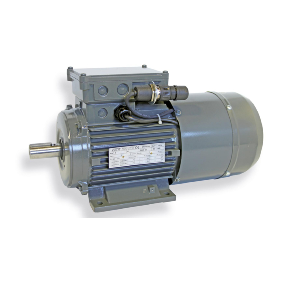
PAGE: 10 3. PRODUCT DESCRIPTION The VASCAT motors of the MAC R series are asynchronous electrical AC machines with a squirrel-cage rotor, circular housing and forced ventilation. They have been specially designed to work in high-dynamics applications that require speed variation. They can be powered by frequency converters or directly from the mains. -
Page 11: Reference Standards
INSTRUCTIONS AND MAINTENANCE MANUAL MAC R MOTORS PAGE: 11 3.2 Reference standards The MAC R motors are designed and manufactured according to the Low Voltage Directive 2006/95/CE and they are to be used in industrial installations as incomplete machinery or machinery component, as provided in the Machines Directive 2006/46/CE. -
Page 12: Definitions
MAC R MOTORS PAGE: 12 The data given in all the documentation provided by VASCAT includes tolerances in accordance with the IEC/EN 60034-1 standard and they are based on test procedures as provided in the IEC 60034-2 standard. The table... -
Page 13: Mounting
INSTRUCTIONS AND MAINTENANCE MANUAL MAC R MOTORS PAGE: 13 3.3.2 Mounting The following are some of the mounting types applicable to the MAC R motors, labelled in accordance with the IEC/EN 60034/7 standard. Mounting Diagram Assembly Mounting Diagram Assembly IM B3 Foot-mounting on IM V1 With flange shaft... -
Page 14: Ip Protection Rating
INSTRUCTIONS AND MAINTENANCE MANUAL MAC R MOTORS PAGE: 14 3.3.3 IP protection rating The protection rating of electrical machines is defined in accordance with IEC/EN 60034-5. Said standard specifies the protection rating of each machine using an ‘IP’ code, which comprises two digits: - First digit: Indicates the protection rating for contact and solid bodies. -
Page 15: Ic Cooling Method
INSTRUCTIONS AND MAINTENANCE MANUAL MAC R MOTORS PAGE: 15 3.3.4 IC Cooling Method The type of cooling used in electrical machines is regulated by the IEC/EN 60034-6 standard. In order to identify the type of cooling used in each motor, it is also given a code similar to the IP protection rating. There are two types of code: full indication (e.g. -
Page 16: Balancing And Vibration Level
INSTRUCTIONS AND MAINTENANCE MANUAL MAC R MOTORS PAGE: 16 3.3.5 Balancing and vibration level The EN 60034-14 standard specifies the test procedures for the acceptance of vibration at factory and the vibration limits for certain electrical machines in specific conditions when they are disconnected from a power machine or charge The standard defines two possible vibration levels for the shaft: type ‘A’... -
Page 17: Insulation Class
INSTRUCTIONS AND MAINTENANCE MANUAL MAC R MOTORS PAGE: 17 3.3.6 Insulation class The insulation rating of an electrical machine is identified on the motor specifications plate by means of a letter in accordance with the IEC/EN 60034-18 standard. The following table summarises the maximum allowed temperature in the installation of a winding in accordance with its insulation rating: Class Maximum temperature... -
Page 18: Nameplate
INSTRUCTIONS AND MAINTENANCE MANUAL MAC R MOTORS PAGE: 18 3.4 Nameplate All MAC R motors carry the following specifications plates: Figure 1: Specifications plate for MAC R motors with shaft heights 80, 90, 100, 112 and 132 Figure 2: Specifications plate for MAC R motors with shaft height 160. The following table contains a description of the different fields of the plates: Pos. -
Page 19: General Specifications
INSTRUCTIONS AND MAINTENANCE MANUAL MAC R MOTORS PAGE: 19 3.5 General specifications 3.5.1 Motor code MAC R series motors are coded as follows: Motor type Series Size Length Connections Y (star) D (triangle) Asynchronous Motor IP54 – IC416 for frequency... - Page 20 INSTRUCTIONS AND MAINTENANCE MANUAL MAC R MOTORS PAGE: 20 Figure 3: Derating factor for an S2-type service CODE: CTT12 EDITION: 01 DATE: MAY 2013 Subject to technical changes without prior notice...
-
Page 21: Mechanical Specifications
INSTRUCTIONS AND MAINTENANCE MANUAL MAC R MOTORS PAGE: 21 3.6 Mechanical specifications 3.6.1 Mounting MAC R series motors are available with the following construction types: FRAME SIZES EN 60034-7 IM B3 IM 1001 IM V6 IM 1031 IM V5 IM 1011... -
Page 22: Ip Protection Rating
Motors that comply with the IP54 protection rating or higher can be installed in damp and dusty industrial environments 3.6.3 Cooling Method The following table summarises the setups available for the MAC R series motors in terms of cooling method and protection rating: COOLING EN60034-6... -
Page 23: Bearings
INSTRUCTIONS AND MAINTENANCE MANUAL MAC R MOTORS PAGE: 23 3.6.5 Bearings MAC R motors include different types of bearings depending on their size (shaft height). The following table summarises the bearings that are considered standard for each model: L10h max P max X max Fr Motor type Bearing... - Page 24 INSTRUCTIONS AND MAINTENANCE MANUAL MAC R MOTORS PAGE: 24 PRECAUTION If the admissible loads are exceeded for the forces on the end of the shaft, damages may occur to the mounting and the machine. Observe the admissible loads according to the data given in the catalogue. Radial load according to speed Figure 4: Admissible radial loads CODE: CTT12 EDITION: 01 DATE: MAY 2013...
-
Page 25: Electrical Specifications
INSTRUCTIONS AND MAINTENANCE MANUAL MAC R MOTORS PAGE: 25 3.7 Electrical specifications 3.7.1 Windings and insulation MAC R motor coil windings are made up of enamelled copper wires rated with F-type insulation class. They are impregnated using single-component epoxy resins that polymerise on the basis of temperature, also class F. -
Page 26: Power-Supply Conditions
Furthermore, the drive switching frequency connected to a MAC R motor must be at least 4 kHz: Otherwise, the rated features of the motor, shown on its specifications plate, must be derated. Please check with VASCAT to determine the resulting values. CODE: CTT12 EDITION: 01 DATE: MAY 2013... -
Page 27: Standard Thermal Protection
INSTRUCTIONS AND MAINTENANCE MANUAL MAC R MOTORS PAGE: 27 3.7.4 Standard thermal protection MAC R motors include a PTC140-type thermistor on their stator windings. It is a solid-state device of the variable resistive type that provides a Contact Open (OFF) / Contact Closed (ON) type logical signal depending on whether or not the temperature of the motor windings exceeds the reference temperature of the sensor, in this case 140°C. -
Page 28: Fan
MAC R series motors are air-cooled using a forced ventilation system that includes an electric fan powered independently from the motor. The fan on MAC R series motors is fitted in an axial position behind the motor and air circulates from back to front. -
Page 29: Accessories
MAC R MOTORS PAGE: 29 3.8 Accessories 3.8.1 Feedback sensors MAC R series motors can be fitted with different types of feedback sensors. As standard models, VASCAT offers the following incremental optical encoders Specifications Type A Type B Type C... -
Page 30: Parking Brake
3.8.2 Parking brake MAC R series motors can be fitted, as an option, with an electromagnetic parking brake to immobilise the motor load safely and in a way that is 100% external to the operation of the motor itself. On certain occasions, this is necessary for safety reasons, e.g. when it is necessary to block the movement of the machine to work on the interior safely or when there is a fault in the converter power supply or other mechanical devices of the installation. -
Page 31: Noise Level
Noise level The technical data sheets VASCAT provides for each motor show the noise level in dB issued by each model. The machines directive specifies a noise level of 80 dB at work posts. The user is responsible for guaranteeing said level using the installation of external absorption devices if necessary. -
Page 32: Shipment, Reception, Transport And Storage
Otherwise, a claim must be filed immediately with VASCAT for the faults that have been seen or for an incomplete shipment. -
Page 33: Transport
INSTRUCTIONS AND MAINTENANCE MANUAL MAC R MOTORS PAGE: 33 4.3 Transport The machine must be transported always in accordance with the following instructions: WARNING Transport and lifting of the machine by the eyebolts only For the correct handling of the motor, eyebolts must be used and must be inserted in the threaded holes on the sides of the housing, which have been machined exclusively for said purpose. -
Page 34: Storage
If the stator winding is damp, its insulation resistance is reduced. This leads to disruptive discharges that can destroy the winding. Furthermore, condensation water may form oxide or mould inside the machine. This is why it is important to follow VASCAT's storage recommendations to the letter. CODE: CTT12 EDITION: 01 DATE: MAY 2013... -
Page 35: Installation And Start-Up
INSTRUCTIONS AND MAINTENANCE MANUAL MAC R MOTORS PAGE: 35 5. INSTALLATION AND START-UP PRECAUTION Damage caused to bearings as a result of long storage periods If the machine has been stored for more than 3 years in good conditions (dry, dust-free place, etc.), the grease on the bearings must be changed, if they need re-greasing, or the bearing should be changed if it is a bearing with lubrication for its entire service life. -
Page 36: Mounting
INSTRUCTIONS AND MAINTENANCE MANUAL MAC R MOTORS PAGE: 36 5.1.2 Mounting Correct mounting is essential to guarantee a long service life for the motor. The following are essential issues that need to be taken into account when anchoring the motor correctly: IM B3 Foot-mounting: a) Ensure that the support base is correctly levelled: the motors must be mounted on a solid, flat base that is perfectly level. -
Page 37: Machine Coupling
The customer is responsible for ensuring the correct alignment of both shafts. VASCAT motor rotors are dynamically balanced using a half-key on the end of the shaft (in accordance with the 60034-14 standard). To ensure the correct balance of the entire transmission unit, all the parts of the transmission system must also be balanced (pulley, coupling, etc.). - Page 38 INSTRUCTIONS AND MAINTENANCE MANUAL MAC R MOTORS PAGE: 38 Figure 8: Fitting the coupling PRECAUTION Damages to the motor bearings If the motor shaft is knocked, the bearings may be damaged. If belts are used for the transmission of the torque or a gear with radial load, make sure that the admissible radial load is not exceeded on the motor shaft.
-
Page 39: Electrical Connections
Before the connection, check the status of the insulation elements of the windings with regard to earth, since long or inappropriate storage or transport may have caused the motor to absorb humidity, which affects the capacity for insulation. The insulation reference values considered safe by VASCAT are as follows: Parameters Reference values... -
Page 40: Connection Strips And Terminals
INSTRUCTIONS AND MAINTENANCE MANUAL MAC R MOTORS PAGE: 40 5.2.1 Connection strips and terminals The motor has a terminal box with the corresponding electrical connection strip and connection bolts for the current of each motor. The following table summarises the different types of strips and terminals that correspond to the standard execution of each axle height of the MAC R motors. -
Page 41: Connection Diagrams
INSTRUCTIONS AND MAINTENANCE MANUAL MAC R MOTORS PAGE: 41 5.2.2 Connection diagrams The connection diagrams of the terminals in the terminal box for standard versions of the MAC R motors in star and triangle configuration are as follows: Freno / Brake / Bremse Ventilador / Fan / Lufter Figure 9: Connection diagram for MAC R motors with a 24 VDC brake. -
Page 42: Power Cables
The inputs of the power cables that are to be connected on the motor terminal box strip and the converter terminals must comply with current regulations. For the protection rating, type of cable-laying, allowed cable diameter, connection, etc., VASCAT recommends the use of symmetrical structure screened cables in accordance with technical specification IEC TS 60034-25. - Page 43 INSTRUCTIONS AND MAINTENANCE MANUAL MAC R MOTORS PAGE: 43 Figure 12: Recommended terminations – Conductor material terminal box S – Cable screen – Earth cable – Motor body – Conductor seals G – EMC gland seal F – Continuous Faraday box The connection between the power cable screen and the motor terminal box must be made using either of the two methods shown in the following figures (on the left with an EMC gland seal and, on the right, with the screen connected to the terminal box using a flange):...
-
Page 44: Connections For The Fan, Thermal Sensors And Accessories
INSTRUCTIONS AND MAINTENANCE MANUAL MAC R MOTORS PAGE: 44 5.2.4 Connections for the fan, thermal sensors and accessories Where necessary, the motor fan cables must be connected in accordance with the voltage specified on the motor specifications plate. They must be connected to the auxiliary terminal strip in the terminals box. To connect the thermal sensors, use terminals of 1.5 mm on the tip and connect them to the corresponding nylon strip. -
Page 45: Start-Up
INSTRUCTIONS AND MAINTENANCE MANUAL MAC R MOTORS PAGE: 45 5.3 Start-up 5.3.1 Preliminary checks Before starting the motor, check the following: - The motor is correctly aligned, fastened and coupled (the belt tension is correct in the case of belt transmission or the radial profile and tooth flank profile is adequate in the case of gear transmission). -
Page 46: Start-Up
3- Gradually increase speed to rated values. 4- After several hours in operation, check that the thermal behaviour of the motor corresponds to the motor service type. If in doubt, please contact VASCAT. CODE: CTT12 EDITION: 01 DATE: MAY 2013... -
Page 47: Maintenance
INSTRUCTIONS AND MAINTENANCE MANUAL MAC R MOTORS PAGE: 47 6. MAINTENANCE This chapter describes the preventive maintenance work that is to be performed on MAC R MOTORS. VASCAT declines all responsibility for faulty maintenance performed by the end user. 6.1 Safety instructions WARNING... -
Page 48: Basic Inspection
If faults are found during the inspection, they must be corrected immediately. Besides this basic inspection, a number of maintenance tasks must be carried out to ensure that the motor has a long service life. The maintenance operations recommended by VASCAT are as follows: 6.2.2... - Page 49 INSTRUCTIONS AND MAINTENANCE MANUAL MAC R MOTORS PAGE: 49 Figure 14: Replacing bearings on MAC R motors (step 3) 4. Remove the rotor from the interior of the stator, taking care not to damage the windings. Figure 15: Replacing bearings on MAC R motors (step 4) 5.
- Page 50 INSTRUCTIONS AND MAINTENANCE MANUAL MAC R MOTORS PAGE: 50 Figure 16: Replacing bearings on MAC R motors (steps 6 and 7) 8. Heat the new bearing to 70°C to make it dilate and easier to insert in the shaft. 9. Insert the new bearing in the shaft. The hot bearing must be inserted fully without the need for hitting it. This operation must be performed as quickly as possible.
-
Page 51: Replacing The Encoder
INSTRUCTIONS AND MAINTENANCE MANUAL MAC R MOTORS PAGE: 51 6.3 Replacing the encoder The procedure for replacing the encoder must be carried out as follows: 1. Remove the fan unit (a) 2. Remove the encoder (b) Figure 17: Replacing the encoder on MAC R motors CODE: CTT12 EDITION: 01 DATE: MAY 2013 Subject to technical changes without prior notice... -
Page 52: Replacing The Brake And/Or Lining
INSTRUCTIONS AND MAINTENANCE MANUAL MAC R MOTORS PAGE: 52 6.4 Replacing the brake and/or lining The procedure for replacing the brake must be carried out as follows: 1. Remove the fan unit (a) 2. Then carefully remove the encoder (b) 3. -
Page 53: Original Spares
MAC R MOTORS PAGE: 53 6.5 Original spares VASCAT supplies subunits of the full motor as original spares for MAC R motors or, where necessary, the entire motor. The spare subunits that are available are listed in the following table:... - Page 54 INSTRUCTIONS AND MAINTENANCE MANUAL MAC R MOTORS PAGE: 54 Figure 21: Spare subunits When a specific original spare is required for a motor from the MAC R series, the following information must be provided: 1. Motor type 2. Motor serial number.
-
Page 55: Operating Faults
If faults appear during the operation of the motor, first of all check the possibility of the errors given in the following tables. If the fault cannot be eliminated with any of the following measures, please contact the technical service at VASCAT. VOLTAGE All the work must be carried out with no voltage connected. - Page 56 INSTRUCTIONS AND MAINTENANCE MANUAL MAC R MOTORS PAGE: 56 Fault Probable cause Corrective action Converter output voltage too high, Check adjustments on frequency converter and frequency too low perform auto-tuning Motor designed to be connected in star format but is connected in triangle Correct connection in terminal box format Overheating...
-
Page 57: Mechanical Faults
INSTRUCTIONS AND MAINTENANCE MANUAL MAC R MOTORS PAGE: 57 6.6.2 Mechanical faults Fault Probable cause Corrective action Rotating parts are rubbing together Determine the cause and readjust the parts Rubbing noise Foreign bodies in the motor If so, repair by manufacturer Damage to bearings Change bearings Rotor imbalance... -
Page 58: Technical Support And Service
MAC R MOTORS PAGE: 58 6.7 Technical support and service For more information or specific technical support, please contact: VASCAT, S.A. P.I. Mas les Vinyes, C/ De l’Esquirol, s/n Apartado 142 08570 Torelló (Barcelona) Tel. +34 93 850 49 38 Fax: +34 93 859 31 31 www.vascat.es... - Page 59 INSTRUCTIONS AND MAINTENANCE MANUAL MAC R MOTORS PAGE: 59 CODE: CTT12 EDITION: 01 DATE: MAY 2013 Subject to technical changes without prior notice...
- Page 60 CTT 12 – ED 01...
Need help?
Do you have a question about the MAC R Series and is the answer not in the manual?
Questions and answers