Table of Contents
Advertisement
Quick Links
Advertisement
Table of Contents

Related Manuals for Decagon Devices EC-20


Summary of Contents for Decagon Devices EC-20
- Page 1 EC-20, EC-10, EC-5 Soil Moisture Sensors User’s Manual Version 10...
- Page 2 Decagon Devices, Inc. 2365 NE Hopkins Court Pullman WA 99163 USA Trademarks: “ECH2O” is a registered trademark of Decagon, Devices, Inc All rights reserved.. ©2001-2010 Decagon Devices, Inc. All rights reserved.
-
Page 3: Table Of Contents
2. About the EC-20, EC-10, EC-5 . .4 The EC-10 and EC-20 ....4 The EC-5 ......4 Sensor Features . - Page 4 EC-20, EC-10 and EC-5 User’s Manual Table of Contents Sensor Calibration Values ... . 16 Troubleshooting ..... . 20 Declaration of Conformity .
-
Page 5: Introduction
EC-10 and EC-20: 0.002m EC-5: 0.001 m VWC in mineral soils, 0.25% in growing media Power: Requirements: EC-10 & EC-20: 2.5VDC @ 2mA to 5VDC @ 7mA EC-5: 2.5VDC - 3.6VDC @ 10mA Output: 10-40% of excitation voltage (250-1000mV at 2500mV excitation) -
Page 6: Contact Information
Operating Environment: EC-10 and EC-20: 0 to 50°C EC-5: -40 to +60 °C Range of Measurement: EC-10 and EC-20: 0 to 40% VWC EC-5: 0 to saturation Sensor dimensions: EC-20: 25.4cm x 3.17cm x .15cm EC-10: 14.5cm x 3.17cm x .15cm EC-5: 8.9cm x 1.8cm x 0.7cm... -
Page 7: Warranty Information
EC-20, EC-10 and EC-5 User’s Manual 1. Introduction Warranty Information The EC-20, EC-10 and EC-5 have a 30-day satisfaction guarantee and a one-year warranty. Seller’s Liability Seller warrants new equipment of its own manufacture against defective workmanship and materials for a... -
Page 8: About The
The EC- 10 and EC-20 have a very low power requirement and high resolution. This gives you the ability to make as... -
Page 9: Sensor Features
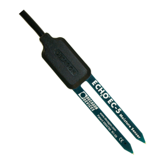
Sensor Fig.1: diagram Fig. 2: EC-5 diagram EC-20 Wiring Diagrams 3.5mm Plug Wiring The EC-20, EC-10 and EC-5 come with a 3.5mm “ste- reo plug” connector. This allows for rapid connection directly to Decagon’s Em50 and Em5 logger and the... -
Page 10: Wiring To Non-Decagon Dataloggers
EC-20, EC-10 and EC-5 User’s Manual 2. About the EC-20, EC-10, EC-5 O Check. Below is a diagram showing the wiring configuration for this connector. Analog Ground Excitation Fig. 2: 3.5mm “Stereo Plug” wiring configuration Wiring to Non-Decagon Dataloggers Models with stripped and tinned leads are pre-config- ured for connecting to non-Decagon dataloggers. -
Page 11: Extended Cable Lengths
Extended cable lengths Decagon supplies 50-foot (15.25m) and 10-foot (3m) extension cables for use with the EC-20, EC-10 and EC- 5 with the 3.5 mm connector . You can safely connect up to 4 of the 50-foot cables without signal attenuation. -
Page 12: Installing The Sensors
Procedure When installing the EC-20, EC-10 and EC-5, it is best to maximize contact between the sensor and the soil. There are two methods to accomplish this. - Page 13 EC-20, EC-10 and EC-5 User’s Manual 3. Installing the Sensors use an augur to reach the desired depth, then use the Installation Kit with extension rods to install the sensor. 2. Use a thin implement like a trenching shovel, gar- dening spade, or flat bar to make a pilot hole in the soil.
-
Page 14: Orientation
EC-20, EC-10 and EC-5 User’s Manual 3. Installing the Sensors The sensor may be difficult to insert into extremely compact or dry soil. If you have difficulty inserting the sensor, try loosening the soil somewhat or wet- ting the soil. Never pound it in! 2. -
Page 15: Collecting Data
EC-20, EC-10 and EC-5 User’s Manual 4. Collecting Data 4. Collecting Data Datalogger Requirements The EC-20, EC-10 and EC-5 sensors are designed to work most efficiently with Decagon’s 5-channel Em5b, Em50, ProCheck or ECH O Check handheld readout. All Decagon readout devices use either a 3.0V or 5V excitation. -
Page 16: Connecting To A Datalogger
Fig. 5: Datalogger configuration Sample Program The following program is an example that can be used with Campbell Scientific’s CR10X datalogger and our EC-20, EC-10 & EC-5 sensors at a 2500mV excitation: ;{CR10X} ; Example ECH2O Datalogger Program for CR10X ; Wiring:... - Page 17 ; probes convert mV output of ECH2O to ; volumetric water content (VWC, m3/m3) ; EC-20: VWC = 0.00069 * mV - 0.29 ; EC-10: VWC = 0.00093 * mV - 0.376 ; EC-5: VWC = 0.00119 * mV - 0.400 ;...
-
Page 18: Scwin (Short Cut) Directions
EC-20, EC-10 and EC-5 User’s Manual 4. Collecting Data SCWin (Short Cut) Directions Following are instructions for using our SCWin (Short Cut) program to read EC-5, EC-10 and EC-20 soil mois- ture sensors. 1. Download EchoCSI.zip from http://www.deca- gon.com/appnotes/EchoCSIappnote.pdf. 2. Unzip the folder EchoCSI.zip. -
Page 19: Calibration
While the factory calibrations for the EC-5 is appropri- ate for almost all soil types, the standard calibrations for the EC-20 and EC-10 sensors do not perform in soils with high sand or salt content. Therefore, for added accuracy we encourage our customers to perform soil- specific calibrations. -
Page 20: Sensor Calibration Values
Sensor Calibration Values Following is a list of the both the millivolt and RAW calibration values for the EC-20, EC-10 and EC-5, where is the volumetric water content, mV is the milli- volt output of the sensor, and where x is the RAW sen- sor output. - Page 21 EC-20, EC-10 and EC-5 User’s Manual 4. Collecting Data to 8 dS/m. Its calibration equations are shown below for mineral soil, potting soil, and rockwool growing media: Dielectric Permittivity Dielectric permittivity can be used to determine volu- metric water content using external published equations such as the Topp equation.
- Page 22 EC-20, EC-10 and EC-5 User’s Manual 4. Collecting Data ø = 11.9 * 10 * mV - 0.401 (2) where mV is the output of the sensor when excited at 2500 mV. Please note that the equation will reach a maximum at ~60% volumetric water content (VWC) in pure water.
- Page 23 EC-20, EC-10 and EC-5 User’s Manual 4. Collecting Data ø = 6.28 * 10 * Raw + 1.37 x 10 * Raw - 0.183(5) for a Decagon datalogger or ø = 2.63 * 10 * mV + 5.07 x 10 * mV - 0.0394(6)
-
Page 24: Troubleshooting
EC-20, EC-10 and EC-5 User’s Manual 4. Collecting Data Troubleshooting If you encounter problems with the EC-20, EC-10 and EC-5, they most likely will manifest themselves in the form of incorrect or erroneous readings. Before contact- ing Decagon about the sensor, do the following: •Check to make sure the connections to the data-... -
Page 25: Declaration Of Conformity
Model Number: EC-10, EC-20, EC-5 Year of First Manufacture:2001 This is to certify that the EC-10, EC-20 and EC-5 O soil moisture sensor, manufactured by Decagon Devices, Inc., a corporation based in Pullman, Washing- ton, USA meets or exceeds the standards for CE compli- ance as per the Council Directives noted above. - Page 26 EC-20, EC-10 and EC-5 User’s Manual Declaration of Conformity...
-
Page 27: Index
EC-20, EC-10 and EC-5 User’s Manual Index Index Accuracy 1 Calibration for EC-10 16 for EC-20 16 for EC-5 16 for mineral soil 17 for potting soil 18 for rockwool 18 Contact information 2 Datalogger 2 connecting to 12 requirements 11... - Page 28 EC-20, EC-10 and EC-5 User’s Manual Index Installation 8 procedure 8 tips 8 Measurement range 2 Mineral soil calibration 17 Orientation of sensor 10 Plug wiring configuration 5 Potting soil 18 Power requirements 1 Program 12 Range 2 Removing the sensor 10 Rockwool 18 Seller’s liability 3...
- Page 29 EC-20, EC-10 and EC-5 User’s Manual Index orientation 10 specifications 1 Sensor orientation 10 Short Cut directions 14 Specifications 1 Troubleshooting 20 Warranty 3 Wiring diagram 5 Wiring diagrams 5...
- Page 30 Delmation Products Blauw-roodlaan 300 2718 SK Zoetermeer 079 - 342 20 41 www.delmation.nl | info@delmation.nl...
Need help?
Do you have a question about the EC-20 and is the answer not in the manual?
Questions and answers