Table of Contents
Advertisement
Quick Links
Advertisement
Table of Contents

Related Manuals for Decagon Devices Dielectric Leaf Wetness Sensor


Summary of Contents for Decagon Devices Dielectric Leaf Wetness Sensor
- Page 1 Operator’s Manual Decagon Devices, Inc. Version: February 29, 2016 — 11:10:55...
- Page 2 Decagon Devices, Inc. 2365 NE Hopkins Court Pullman WA 99163 Phone: 509-332-5600 Fax: 509-332-5158 Website: www.decagon.com Email: support@decagon.com or sales@decagon.com Trademarks: “ECH O” is a registered trademark of Decagon Devices, Inc. All Rights Reserved c 2007-2014 Decagon Devices, Inc. All Rights Reserved...
-
Page 3: Table Of Contents
CONTENTS Contents 1 Introduction 1.1 Customer Support ....1.2 About This Manual ....1.3 Warranty . -
Page 4: Introduction
1 INTRODUCTION Introduction Thank you for choosing Decagon’s Dielectric Leaf Wetness Sensor. We designed this sensor to accurately and affordable measure the duration of leaf-surface wetness. This manual should help you un- derstand the sensor features and how to use it successfully. -
Page 5: Warranty
1 INTRODUCTION Warranty The Dielectric Leaf Wetness Sensor has a 30-day satisfaction guar- antee and a one-year warranty on parts and labor. Your warranty is automatically validated upon receipt of the instrument. Note: The one year service plan activates when Decagon ships the instrument and not at the time of software installation. -
Page 6: About The Leaf Wetness Sensor
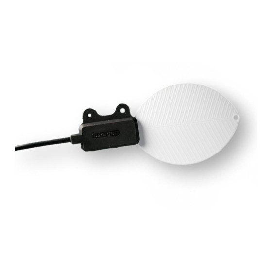
2 ABOUT THE LEAF WETNESS SENSOR About the Leaf Wetness Sensor The LWS measures leaf surface wetness by measuring the dielectric constant of the sensor’s upper surface (see Section 5 for a more thor- ough explanation). It has a very low power requirement, which gives you the ability to make as many measurements as you want over a long period of time (such as a growing season) with minimal bat- tery usage. - Page 7 2 ABOUT THE LEAF WETNESS SENSOR Figure 1: The Leaf Wetness Sensor...
-
Page 8: Collecting Data
3 COLLECTING DATA Collecting Data Installing the Sensor The LWS is designed to be deployed either in the canopy or on weather station masts. There are two holes in the non-sensing por- tion of the sensor body for mounting. The holes can be used with either zip ties or with 4-40 bolts. -
Page 9: Data Logger Requirements
3 COLLECTING DATA Data Logger Requirements The LWS works with Decagon’s 5-channel Em50 or Em50R data log- gers. It can also be adapted for use with other data loggers, such as those from Campbell Scientific, Inc. (See Appendix A for a sample program.) The sensor requires an excitation voltage in the range of 2.5 to 5 volts. -
Page 10: Extending The Sensor Leads
3 COLLECTING DATA Figure 3: Sensor wiring diagram Extending the Sensor Leads Extension cables for the LWS are available from Decagon in 10 and 50 foot (3 and 15 meter) lengths. The leads can be extended up to 250 feet without signal attenuation. When using these extension cables in an unprotected environment, the junctions between cables must be waterproofed. -
Page 11: Interpreting Data
4 INTERPRETING DATA Interpreting Data Most leaf wetness applications (disease forecasting, etc.) do not re- quire knowledge of the amount of water on the surface - only if there is any water on the surface. To make this determination, a sensor output threshold corresponding to the minimum wet state must be identified. -
Page 12: Understanding Data From The Em50
4 INTERPRETING DATA cause the dry output to rise. We recommend that the sensor be cleaned using a moist cloth periodically, or when you detect elevated dry output. Understanding Data from the Em50 With Decagon’s Em50 and Em50R data loggers, users have multi- ple options for interpreting data. -
Page 13: Unprocessed Data File
4 INTERPRETING DATA cleaned. Column 3: The final reading (in raw counts) of the LWS during the wake interval. So, if again a 30 minute wake interval has been chosen, the number in column 3 is the output in raw counts from the LWS during the last minute of that 30 minute period. -
Page 14: Datatrac3 File
4 INTERPRETING DATA Column 3: The final reading (in raw counts) of the LWS during the wake interval. (See column 3 description under precessed the files above) 4.1.3 DataTrac3 File When you download the DataTrac3 file format (.dxd), a single 10 digit number downloads for each sensor. -
Page 15: Lws Theory
5 LWS THEORY LWS Theory How the LWS Works The LWS measures the dielectric constant of a zone approximately 1 cm from the upper surface of the sensor. The dielectric constant of water (80) and ice (5) are much higher than that of air (1), so the measured dielectric constant strongly dependends on the presence of moisture or frost on the sensor surfaces. - Page 16 5 LWS THEORY with a hydrophobic cuticle. The sensor should match the wetness state of these types of leaves well, but may not match the wetness duration of leaves with plentiful leaf hairs or less waxy cuticles. It is impossible for any sensor to accurately mimic the properties of all leaves.
-
Page 17: Appendix A: Sample Csi Program
6 APPENDIX A: SAMPLE CSI PROGRAM Appendix A: Sample CSI Program ;{CR23X} ;Program to read Decagon’s Dielectric Leaf Wetness ;Sensor (LWS) ;Wiring: white to EX1, red to 1H, shield to gnd ;This program separates LWS output into three bins ;bin 1 = output < 330mV - dry sensor ;bin 2 = 330mV <... - Page 18 6 APPENDIX A: SAMPLE CSI PROGRAM 5: Histogram (P75)^15793 1: 1 Reps 2: 3 No. of Bins 3: 0 Open Form 4: 1 Bin Select Value Loc [ LWS_mV ] 5: 0 Frequency Distribution 6: 330 Low Limit 7: 337 High Limit *Table 2 Programs 02: 0.0000 Execution Interval (seconds) *Table 3 Subroutines...
-
Page 19: Declaration Of Conformity
Year of First Manufacture: 2006 This is to certify that the Dielectric Leaf Wetness Sensor, manufactured by Decagon Devices, Inc., a corporation based in Pullman, Washington, USA meets or exceeds the standards for CE compliance as per the Council Directives noted above. - Page 20 Index Contact Information, 1 Customer Support, 1 Data, 5 Interpretation, 8 Data Logger, 3 Data from Non-Decagon loggers, Extending Sensor Leads, 7 Requirements, 6 Sample CSI program, 14 Wiring Configuration, 6 DataTrac3, 11 Files, 11 Dielectric Measurement, 12 ECH2O Utility, 9 Processed Data File or tab delim- ited text file, 9 Unprocessed Data File, 10...
Need help?
Do you have a question about the Dielectric Leaf Wetness Sensor and is the answer not in the manual?
Questions and answers