Table of Contents
Advertisement
Advertisement
Table of Contents

Related Manuals for digicon dTower


Summary of Contents for digicon dTower
- Page 1 Produ t Manual Tower...
- Page 3 Tower Revision Date Reviser History July 2,2019 Anderson Silva New connection system of electrical panel; Ÿ Ÿ Vinícius Duarte DIP table update; Ÿ Ÿ Gustavo Enedir Software update; Ÿ Ÿ Leandro Dandolini Dimensions; Ÿ Ÿ Nicholas Reis Preventive Maintenance Ÿ Ÿ...
- Page 4 All rights reserved. No part of this publication may be reproduced, transmitted, transcribed, stored in a retrieval system, translated into any language or computer language in any electronic, magnetic, optical, chemical, manual way, or otherwise, without express written permission from Digicon S.A. Code: 069.31.221 Revision: 11 - English Digicon S.A.
-
Page 5: Table Of Contents
................Symbols .................. Installation site ................. General maintenance precautions ..........Guidelines ..................Walkthrough ..................5. Características do dTower ..............5.1 Pictogramas do dTower .............. dTower Features .................. Unboxing ................. Pre-installation ................Fixation to the floor ..............Fixation of doors .............. -
Page 6: Introduction
Read this manual carefully because it contains important information that will help you understand the processes of installation, operations, maintenance, and unboxing. Correct installation and maintenance ensure equipment operation and increase the useful life of its components. Correct equipment installation and operation guarantee proper functioning according to Digicon specifications. -
Page 7: Safety Instructions
Tower Safety Instructions Symbols You may find this symbol in the product manual. It indicates important instructions concerning operation or maintenance. You may find this symbol attached to the product. It indicates a powered terminal where dangerous voltage may be present. You may find this symbol attached to the product. -
Page 8: Installation Site
Tower Electric shock can cause personal injuries or even death. Avoid direct contact with dangerous voltages at all times. The protective grounding connection, when offered, is essential for a safe operation and must be checked before connecting the equipment to the power grid. Know the following warnings and safety guidelines: Dangerous voltages Only qualified technical professionals can install or replace the equipment. -
Page 9: General Maintenance Precautions
Tower General maintenance precautions WARNING Avoid electric shock! Opening or removing the doors of this equipment can expose it to dangerous voltages. WARNING To reduce the risk of electric shock, before maintenance, turn off the power of the equipment by moving the circuit breaker key to the position OFF. -
Page 10: Guidelines
Digicon recommends using the maximum-security level whenever children use the Ÿ equipment. Digicon reserves its right to alter its products at any moment to adapt them to more Ÿ recent technological advancements. Digicon maintains its right to alter the information contained in this manual without Ÿ... -
Page 11: Pictogramas Do Dtower
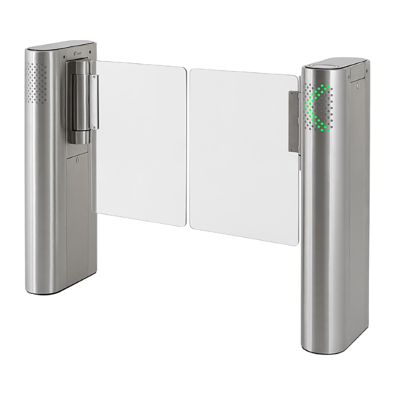
Tower dTower features Innovative design, alongside the dGate and dFlow lines; Robust solution, with motorized system and control with proprietary technology; Reinforced structure for fixing it to the ground; Available in stainless steel and carbon steel painted in powdered epoxy;... - Page 12 Tower dTower pictograms has two pictograms: direction and operation. dTower A) Operational pictogram (top): The operational pictogram is installed on the upper part of the equipment and is represented by a sequence of LED lights in two colors, depending on the direction of the operational flow and validation group, if it exists.
-
Page 13: Unboxing
In case of missing pieces, immediately contact the Digicon representative responsible for the sale. Ÿ Two people are necessary to remove the equipment from the box;... - Page 14 Tower The distance between doors depends on their sizes. Doors must be adjusted so to have a small space between them of about 30mm. Such space is important to ensure that, even closed, the door will not injure the user. Conduits with 50 mm diameter 4"x4"...
-
Page 15: Fixation To The Floor
Tower Fixation to the floor The image below indicates the points for fixing the product to the floor. The surface must be steady and leveled to ensure good performance for the passage- controlling sensor and to maintain the doors aligned. Fixing can be done through mechanical bolts, also known as parabolts, or through chemical anchorage. - Page 16 Long door Short door 90° 90° NOTE - Digicon meets the norm ABNT NBR 9050: Accessibility to buildings, furniture, space, and urban equipment. Step-by-step: 1. Use the 12mm (0,47'') drill to drill the hole with depth of 90mm (Threaded bar M10);...
- Page 17 Tower NOTE - We recommend using chemical anchorage; however, if you prefer parabolts, make sure the floor is adequate.
-
Page 18: Fixation Of Doors
Tower 6.4 Fixation of doors dTower is packaged with the doors unassembled, that is, they accompany the equipment separately in order to avoid damage. To install/fixate the doors, follow the step-by-step below: 1º Place the screw (1) only in the upper part, in the fastener hole (2);... -
Page 19: Labels
Tower 6.4.1 Labels Alongside the equipment, there are identification labels for passage, which are blue and yellow circles: Blue: Identify passage for people with special needs (PNE), with a passage space of 920mm. Yellow: Identify passage for people with special needs, with a passage space of 520mm. Identification labels for pasagem NOTE –... -
Page 20: Accessing Dtower After Assembly
Tower Accessing dTower after assembly WARNING Avoid electric shock! Opening or removing the doors of this equipment can expose it to dangerous voltages. WARNING To reduce the risk of electric shock, before maintenance, turn off the power of the equipment by moving the circuit breaker key to the position OFF. -
Page 21: Electrical Connection
Leave all maintenance services to qualified technical professionals. Interconnection cables can be found in the and must pass through the dTower R ducts as seen below: Interconnection duct for signal cables and DC charge: 037.12.909 - Interconnection signal cable and DC charge dTower Ÿ... - Page 22 NOTE - On the cable itself there are rings identifying where each cable must be connected. NOTE - Separate the electric network from the logical network. NOTE - Digicon provides interconnection cables with 3 meters of length. Ÿ The depth of the ducts must be sized so that the cables are enough. Ÿ...
- Page 23 OFF. Leave all maintenance services to qualified technical professionals. The connection must follow the figure below: Digicon recommends using the norm NBR 5410 as reference for electrical installations of equipment pieces. Power cables of power supply must be connected to the circuit breaker and the ground cable in yellow/green terminal.
-
Page 24: Connection Of Control Signs
Tower Connection of control signals WARNING To reduce the risk of electric shock, before maintenance, turn off the power of the equipment by moving the circuit breaker key to the position OFF. Leave all maintenance services to qualified technical professionals. Enabling dry contact with 2 relays: Dry contact Enab. - Page 25 Tower Enabling by solid state (positive, positive voltage): Enab. exit VDC = 5~24V Enab. entry Integrator controller 654321 Controller board Enabling solid state (negative): Vdc = 5~24V Enab. exit Enab. entry 54321 Integrator controller Controller board...
- Page 26 Tower Confirming passage V c - True logical level, configured in “disk emulation” DIP Ds2 n.7 in ON. Positive digital input Integrator controller 4321 Entry confirmation Controller board Exit confirmation Confirming passage - Negative Negative digital input Integrator controller 4321 Controller board...
- Page 27 Tower Confirming passage by disk emulation: Confirmation of entry Confirmation of exit In this operation mode, any of the passage confirmation outputs – output Rl1 or Rl2 – can be used to activate an electromechanical counter in order to count the passage flow in both directions of the equipment.
-
Page 28: Dtower Operation
OFF. Leave all maintenance services to qualified technical professionals. dTower R will always be the master module in the blockage. In this module the controller board is installed – it is responsible for controlling the operation of the blockage. - Page 29 Retention time of card in the box for reading: 2s Confirming passage by disk emulation Confirming passage by pulse dTower operational mode CLIP operational mode NOTE - The grey squares (in bold) in the tables above show the standard configuration, that is, factory settings.
- Page 30 20ms and another of 150ms with interval of 200ms between them. In this situation, the would count two accesses, allowing two dTower people to pass in sequence without closing the door. NC Pulse Pulso do tipo NF Voltage (V) Tens ão (V)
- Page 31 Tower No Pulse Pulso do tipo NA Voltage (V) Tens ão (V) 0,00 0,20 0,40 0,60 0,80 1,00 0,00 0,10 0,20 0,30 0,40 0,50 Tempo (ms) Time (s) Tempo (s) 7.4.2.1 Configurable functions (via inputs) Free pass: Activation: send entry and exit commands at the same time and keep them active. The free pass mode is appropriate for situations that demand that the system remains cleared for an indeterminate amount of time and without passage control.
-
Page 32: Configurable Functions (Via Ds1)
Tower Switch or ralay NOTE - Switch or relay with two poles and one activation 7.4.2.1 Configurable functions (via DS1) a) Sound signal for invasion: Activation: DS1-P1 at ON. This feature, when activated, emits sound signals when the following events occur: Invasion by any side of the blocked area with the door closed;... - Page 33 Tower a) Passage with or without invasion: Selection: DS1-P3 at ON allows invasion, at OFF it does not. This feature defines if, in standby, the blockage accepts or not the invasion, that is, if it allows or not the obstruction of its sensors.
-
Page 34: Configurable Functions (Via Ds2)
Tower 7.4.2.3 Configurable functions (via DS2) a) Waiting time after passage: Selection: DS2-P1, DS2-P2. This feature allows selecting the waiting time before closing the door after a valid passage. Times can be 0.5 seconds, 1.25 seconds, 2 seconds or Smart Speed. In the Smart Speed option, the system measures the passage speed and calculates the time for a person to go over the blockage in safety. - Page 35 Selection: DS2-P8 It selects the equipment operational mode: dTower mode, where the sensors track the user throughout the passage; Clip mode, which operates without the help of sensors to control passage and is based only on passage timeout for closing the doors.
-
Page 36: Technical Characteristics
Tower 8. Technical characteristics 8.1 Dimensions (36,220") /520 (20,472") (8,858") 400(15,748") NOTE - Measures are provided in millimeters and (inches). -
Page 37: Other Information
Tower Other information Technical Caracteristics Power supply (inner source) 100 - 240 VAC; 4,6 – 3,3 A Power supply (outer source) 24 VDC; 5 A (+/-5%) ( one source per module Frequency 50/60 Hz Average time for opening/closing According to configuration door Operating temperature 0°C e 50°C... -
Page 38: Trouble Shooting
(Reference turns off. the AC supply electrical connections). Emitter sensors are misaligned Check alignment of dTower R and with receivers. Intermittent sound alarm and Supply and signals of dTower R Check connection between cable side and upper pictograms sensors. - Page 39 Calibrate doors dTower doors misaligned. Door calibration. Check connection of CN12 and CN13 on dTower control board. Check CN3 and CN8 on dTower R interconnection board. Check connection of CN1 on dTower R side pictograms Control or supply cable dTower side pictogram.
- Page 40 Tower Check connection of CN12 and CN13 on dTower control board. Check CN4 and CN8 on dTower R and T interconnection board. Check connection of CN1 on Control or supply cable dTower T side pictograms dTower side pictogram. disconnected turned off.
-
Page 41: Preventive Maintenance
Tower Preventive maintenance To estimate the intervals between preventive maintenances, we assumed 1600 passages/day in a 30-day month. These are reference values and can change according to the utilization mode of each customer, who then must make the necessary changes to obtain their own results. - Page 42 Tower Records of Preventive Maintenance: Manufacturer Company: Contacts: Digicon +55 51 3489 7000 www.digicon.com.br Product Model: Code: Serial number: Installation Company: Contacts: Date: Action Date Responsible Signature...
-
Page 43: Cleaning
Tower Cleaning 11.1 Maintenance and preservation of stainless steel: Do not use chemical products, bleaches, or household cleaning products. Routine cleaning: The best products to preserve stainless steel are water, soap, mild and neutral detergents and ammonia-based removers diluted in warm water and applied with a soft cloth or a nylon sponge. -
Page 44: Maintenance And Preservation Of Polycarbonate
Tower Intense dirt/Prominent stains: Apply warm or hot detergent or an ammonia-based remover (domestic removers) and water solution. If this is not enough to remove burnt food or charred deposits, use more aggressive products, such as caustic soda-based removers used in domestic cleaning. 11.2 Maintenance and preservation of polycarbonate (doors) Routine cleaning: Choose a dry day (preferably with low humidity) because it will be... -
Page 45: Warranty And Technical Assistance
Tower 12. Warranty and Technical Assistance Digicon is responsible for the project, skilled labor, and quality of the materials used in the manufacturing of our products, ensuring that the equipment and all parts are free of manufacturing defects or problems. Digicon commits itself to replace or repair, as we choose, any part or equipment presenting manufacturing defects without any costs to the buyer, in our factory in Gravataí... -
Page 46: Notes
Tower Notes:... - Page 47 Tower...
- Page 48 Factory, Technical Assistance, Sales Rua Nissin Castiel, 640 - Distrito Industrial. Gravataí/RS ZIP CODE 94045-420 Sales: (0xx51) 3489.8700 / 3489.8745 Technical Assistance: (0xx51) 3489.8903 E-mail: vendas.acesso@digicon.com.br Office/ São Paulo Development, Technical Assistance, Sales Rua São Paulo, 82 - Alphaville. Barueri/SP ZIP CODE 06465-130 Phone: (0xx11) 3738.3500...
Need help?
Do you have a question about the dTower and is the answer not in the manual?
Questions and answers