
Related Manuals for Panasonic Mini DV


Summary of Contents for Panasonic Mini DV
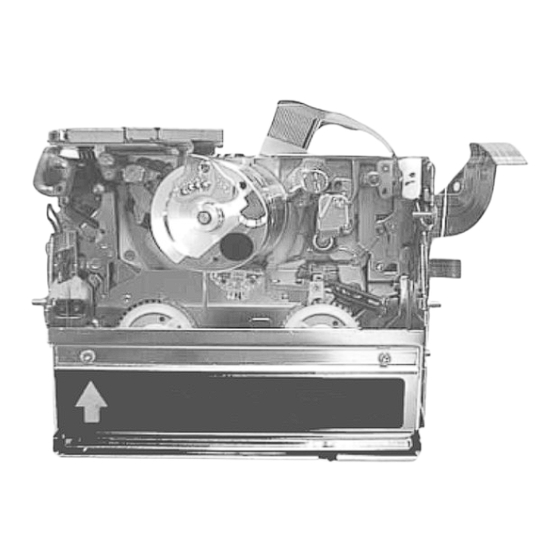
- Page 1 ORDER NO. VMD0109026C8 Digital Video Camera/Recorder Q-MECHANISM • (Including Q1, Q2&Q3) © 2001 Matsushita Electric Industrial Co., Ltd. All rights reserved. Unauthorized copying and distribution is a violation of law.
- Page 2 1 MECHANICAL PARTS LOCATION 1.1 UPPER SIDE...
- Page 3 1.2 BOTTOM SIDE 1.3 SENSOR POSITION...
- Page 4 2 SERVICING FIXTURES& TOOLS 2.1 FIXTURES& TOOLS FOR DISASSEMBLY& ASSEMBLY No. Parts number Parts Name Q´ty New Remarks VFK1390 Precision Driver • VFK1444 Gear Driver • VFK1444Q2 Gear Driver for Q2 & Q3mecha. • VFK1650 Cut Washer Jig(0.86) • VFK1649 Cut Washer Jig(0.65) •...
- Page 5 2.3 MAINTENANCE FOR CAPSTAN TILT ADJUSTMENT JIG. 1. Keep applying oil for preventive oxidation on base block. Glove should be used when you apply oil. 2. Do not apply pressure to this jig. 3. If Brightness of LED become weak, Battery (SUM4 X 2) in the top of box should be changed.
- Page 6 3 DISASSEMBLY PROCEDURE 3.1 PREPARATION FOR DISASSEMBLY...
- Page 7 3.2 DISASSEMBLY PROCEDURE Item Fig. Procedure Cassette Up Unit. Fig. D1-1 1) Remove 3 screws. (Q1 &2 have 4 screws) Fig. D1-2 2) Take coupling portion off from both S &T sides. H Amp Unit. Fig. D2-1 1) Remove a screw from Shield case. (Only Q1 &...
- Page 8 4) Remove 2 washers and take Tension Plate. *20 T4 Guide , Eject Lever , Pulley Cover & Fig. D20- 1) Remove a screw and take T4 Guide out. Pulley. Fig. D20- 2) Remove a washer and take Eject Lever out. Fig.
- Page 9 Fig. D2-1 Fig. D2-2 Fig. D2-3...
- Page 10 Fig. D3-1 Fig. D3-2 Fig. D3-3...
- Page 11 Fig. D4-1 Fig. D4-2 Fig. D4-3...
- Page 12 Fig. D5-1 Fig. D5-2 Fig. D6-1...
- Page 13 Fig. D6-2 Fig. D7-1 Fig. D7-2...
- Page 14 Fig. D7-3 Fig. D8...
- Page 15 Fig. D9 Fig. D10 Fig. D11 Fig. D12 Fig. D13...
- Page 16 Fig. D14 Fig. D15 Fig. D16 Fig. D17-1...
- Page 17 Fig. D17-2 Fig. D18-1 Fig. D18-2...
- Page 18 Fig. D19 Fig. D20-1 Fig. D20-2...
- Page 19 Fig. D20-3 Fig. D21...
- Page 20 4 ASSEMBLY PROCEDURE 4.1 ASSEMBLY PROCEDURE Item Fig. Grease Procedure S3 Base U. Fig. A1 1) Put S3 Base U on and tighten a screw. T4 Guide , Eject Lever, Pulley Cover Fig. • 1) Put hole of T4 Guide to hole of chassis and tighten a screw. &...
- Page 21 Pinch Arm & Center Gear Fig. 1) Put Center Gear Spacer on shaft of chassis. A16-1 2) Put Center Gear on. Fig. • 3) Make full loading position and put Pinch arm on, then put a washer on. A16-2 Sub Chassis Unit Fig.
- Page 22 How to use washer jigs. Item Fig. Procedure Washer Jigs Fig. W1-1 1) Each Washers. Fig. W1-2 1) Put a washer on tip of Jig. Fig. W1-3 1) Put Jig on shaft. Fig. W1-4 1) Put a washer on shaft by pressing Jig. Fig.
- Page 23 Fig. W1-3 Fig. W1-4 Fig. A1...
- Page 24 Fig. A2-1 Fig. A2-2 Fig. A2-3...
- Page 25 Fig. A2-4 Fig. A3 Fig. A4...
- Page 26 Fig. A5-1 Fig. A5-2...
- Page 27 Fig. A6 Fig. A7 Fig. A8...
- Page 28 Fig. A9 Fig. A10-1 Fig. A10-2...
- Page 29 Fig. A11 Fig. A12 Fig. A13...
- Page 30 Fig. A14 Fig. A15-1 Fig. A15-2...
- Page 31 Fig. A15-3 Fig. A16-1 Fig. A16-2...
- Page 32 Fig. A17-1 Fig. A17-2 Fig. A17-3...
- Page 33 Fig. A17-4 Fig. A18-1 Fig. A18-2...
- Page 34 Fig. A18-3 Fig. A19-1 Fig. A19-2...
- Page 35 FIg. A19-3 Fig. A20-1 Fig. A20-2...
- Page 36 Fig. A20-3 Fig. A21-1 Fig. A21-2...
- Page 37 5 MECHANICAL ADJUSTMENT PROCEDURE 5.1 MECHANICAL ADJUST TABLE Item Confirmation of Linearity Confirmation of Capstan tilt S3 Base Sub Chassis Adjustment Tape Running Adjustment B.E.R. Value Adjustment adjustment MECHANISM • CHASSIS Cassette Up Unit. *3 H Amp Unit. • Cylinder Unit •...
- Page 38 5.2 MECHANICAL ADJUSTMENT PROCEDURE Item Equipment Fig. Procedure Confirmation of Tape 1. Alignment Tape Fig. 1) Confirm each post position in playback mode. Running (PAL: VFM3110EDS/NTSC: AD1-1 VFM3010EDS) Fig. 2) Confirm condition of tape regulation in playback & review 2. Post Adjustment AD1-2 mode.
- Page 39 Fig. AD2-1 Fig. AD2-2 Fig. AD2-3 Fig. AD4-1 Fig. AD4-2...
- Page 40 Fig. AD5-1 Fig. AD5-2 Fig. AD6-1...
- Page 41 Fig. AD6-2...
- Page 42 6 EXPLODED VIEWS 6.1 Q1& Q2 VCR MECHANISM SECTON (1)
- Page 43 6.2 Q1& Q2 VCR MECHANISM SECTION (2)
- Page 44 6.3 Q3 VCR MECHANISM SECTION (1)
- Page 45 6.4 Q3 VCR MECHANISM SECTION (2)
- Page 46 7 REPLACEMENT PARTS LIST 7.1 Q1& Q2 VCR MECHANISM SECTION (1) PARTS LIST Ref. No. Part No. Part Name & Description Remarks VEG1495 CYLINDER U. DFX25A7VWB CAPSTAN U. VDG1284 DRIVE GEAR VDG1285 CENTER GEAR VDG1290 INTERFACE GEAR (C) VDG1291 INTERFACE GEAR (D) VDG1295 DECELERATION (A) NV-EX1,NV-DS77...
- Page 47 VXL2814 EJECT LEVER U. VXL2815 TENSION LEVER U. VXL2816 EJECT ARM U. VXL2897 PINCH ARM U. VXL2818 IDLER U. VYK8485 HEAD AMP U. NV-EX1 VYK8244 HEAD AMP U. NV-DS77 VYK8886 HEAD AMP U. NV-DS99/990,NV-DS33 VYK9102 HEAD AMP U. NV-EX3 VSC4802 SHIELD CASE NV-EX1 VSC4758...
- Page 48 B632 VHD1162 SCREW NV-EX1,NV-DS77,NV-DS99/990,NV-DS33 B633 VHD1162 SCREW NV-EX1,NV-DS77,NV-DS99/990,NV-DS33 B634 XQN16+B12 SCREW NV-EX1,NV-DS77,NV-DS99/990,NV-DS33 N601 VHN0324 W601 VMX2028 WASHER W602 VMX2751 WASHER W603 VMX2752 WASHER W604 VMX2392 WASHER W605 VMX2028 WASHER W606 VMX2028 WASHER W607 VMX2028 WASHER W608 VMX2028 WASHER W609 VMX2028 WASHER W610 VMX2028...
- Page 49 B659 VHD1314 SCREW B660 VHD1314 SCREW B661 VHD1163 SCREW B662 VHD1163 SCREW 7.3 Q3 VCR MECHANISM SECTION (1) PARTS LIST Ref. No. Part No. Part Name & Description Remarks VEG1620 CYLINDER U. NV-EX21,NV-DS68/88/89/25/12/15/150,NV-MX2/8/300/1/3/5/7 VEG1619 CYLINDER U. NV-GS1/3/4/5,NV-GX7 VEG1495 CYLINDER U. NV-DS35/55 DFX25A7VWC CAPSTAN U.
- Page 50 VXA6136 PINCH BEETLE VXA6137 RELEASE BEETLE VXA6138 RAIL U. VXA6134 CHASSIS RADON U. Q3 MECHANISM VXA6184 S3 BASE U. VXL2814 EJECT LEVER U. VXL2815 TENSION LEVER U. VXL2816 EJECT ARM U. VXL2897 PINCH ARM U. VXL2818 IDLER U. VYK8886 HEAD AMP U. NV-DS35/55 B501 VHD1155...
- Page 51 B530 XQN16+B2 SCREW B535 XQN16+B3 SCREW NV-DS35/55 N501 VHN0324 W501 VMX2028 WASHER W502 VMX2028 WASHER W503 VMX2028 WASHER W504 VMX2028 WASHER W505 VMX2028 WASHER W506 VMX2028 WASHER W507 VMX2028 WASHER W508 VMX2751 WASHER W509 VMX2752 WASHER W510 VMX2392 WASHER W511 VMX2028 WASHER 7.4 Q3 VCR MECHANISM SECTION (2)
Need help?
Do you have a question about the Mini DV and is the answer not in the manual?
Questions and answers