Table of Contents
Advertisement
Quick Links
DMC 60™ Reference Manual
Revised November 15, 2016
This manual applies to the DMC 60 rev. A
Overview
The DMC 60 is an electronic speed controller designed for driving brushed DC motors. It utilizes synchronous
rectification to efficiently produce a variable output voltage that's controlled by a PWM Input Signal. This makes
the DMC 60 ideal for use in robotics applications, including FIRST Robotics Competition.
DOC#: 410-334-1
Arrow.com.
Downloaded from
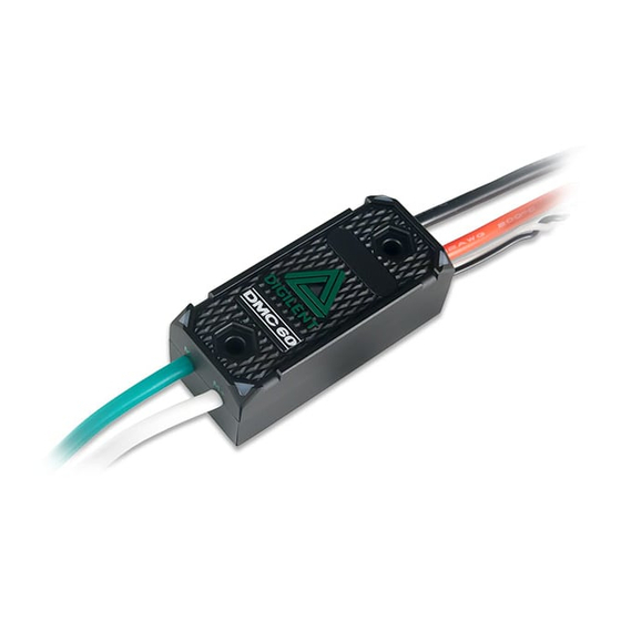
Figure 1. DMC 60 components.
The DMC 60.
Copyright Digilent, Inc. All rights reserved.
Other product and company names mentioned may be trademarks of their respective owners.
Sealed, ruggedized, and compact aluminum case
Tie-wrap and through-bolt mounting – drop-in
replacement for Victor SP controller
Four multi-color LED indicators sequence to
indicate speed, direction, and status for easier
debugging
Brake / Coast Calibration button enables one-
touch setting changes and calibration
Large gauge input/output cables with flexible
silicone insulation
Integrated thermal sensing and protection –
current-foldback to prevent overheating and
damage
15.625 kHz output switching frequency ensures
smooth and precise motor control
1300 Henley Court
Pullman, WA 99163
509.334.6306
www.digilentinc.com
Page 1 of 7
Advertisement
Table of Contents

Related Manuals for Digilent DMC 60


Summary of Contents for Digilent DMC 60
- Page 1 This manual applies to the DMC 60 rev. A Overview The DMC 60 is an electronic speed controller designed for driving brushed DC motors. It utilizes synchronous rectification to efficiently produce a variable output voltage that’s controlled by a PWM Input Signal. This makes the DMC 60 ideal for use in robotics applications, including FIRST Robotics Competition.
- Page 2 PWM Input Signal Logic Low Threshold PWM Output Frequency 15625 Mechanical Dimensions and Mounting Information Copyright Digilent, Inc. All rights reserved. Page 2 of 7 Other product and company names mentioned may be trademarks of their respective owners. Arrow.com. Arrow.com.
- Page 3 When powering the DMC 60 via a Power Distribution Panel (PDP) this typically means connecting the Red Wire of the DMC 60 to the Red Terminal of the PDP and the Black Wire of the DMC 60 to the Black Terminal of the PDP.
- Page 4 Motor Controller LEDs The DMC 60 contains four RGB (Red, Green, and Blue) LEDs and one Brake / CAL LED. The four RGB LEDs are located in the corners and are used to indicate status during normal operation, as well as when a fault occurs. The Brake / CAL LED is located in the center of the triangle, which is located at the center of the housing, and is used to indicate the current Brake/Coast setting.
- Page 5 Brake/Coast Mode How the DMC 60 responds when it detects a neutral input signal, or the loss of the input signal, depends on the Brake / Coast setting. When the DMC60 is configured for Brake Mode the M+ and M- leads are internally shorted when a neutral signal is detected, which will cause an attached motor to resist rotation.
- Page 6 Internal Temperature Monitoring and Over Temperature Protection The DMC 60 features an onboard thermistor, which allows the temperature of the circuit board to be continuously monitored. When the motor controller detects that the temperature of the circuit board has exceeded 70°C it will begin to decrease the duty cycle of the output.
- Page 7 Green Blue Cyan / Aqua Copyright Digilent, Inc. All rights reserved. Page 7 of 7 Other product and company names mentioned may be trademarks of their respective owners. Arrow.com. Arrow.com. Arrow.com. Arrow.com. Arrow.com. Arrow.com.
Need help?
Do you have a question about the DMC 60 and is the answer not in the manual?
Questions and answers