Table of Contents
Advertisement
Quick Links
chipKIT™ WF32™ Board Reference Manual
Revised September 16, 2013
This manual applies to the chipKIT WF32 rev. B
Overview
The chipKIT WF32 is based on the popular Arduino™ open-source hardware prototyping platform and adds the
performance of the Microchip PIC32 microcontroller. The WF32 is the first board from Digilent to have a WiFi
MRF24 and SD card on the board both with dedicated signals. The WF32 board takes advantage of the powerful
PIC32MX695F512L microcontroller. This microcontroller features a 32-bit MIPS processor core running at 80Mhz,
512K of flash program memory, and 128K of SRAM data memory.
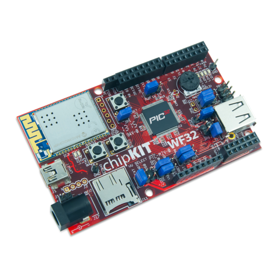
The chipKIT WF32 board.
The WF32 can be programmed using the Multi-Platform Integrated Development Environment (MPIDE), an
environment based on the original Arduino IDE, modified to support PIC32. It contains everything needed to start
developing embedded applications. The WF32 features a USB serial port interface for connection to the MPIDE and
can be powered via USB or by an external power supply. In addition, the WF32 is fully compatible with the
advanced Microchip MPLAB
the Microchip PICkit™3 or the Digilent chipKIT PGM. The WF32 is easy to use and suitable for both beginners and
advanced users experimenting with electronics and embedded control systems.
DOC#: 502-273
Other product and company names mentioned may be trademarks of their respective owners.
®
IDE and works with all MPLAB compatible in-system programmer/debuggers, such as
Copyright Digilent, Inc. All rights reserved.
Microchip® PIC32MX695F512L microcontroller (80
MHz 32-bit MIPS, 512K Flash, 128K SRAM)
Microchip MRF24WG0MA WiFi module
microSD card connector
USB 2.0 OTG controller with A and micro-AB
connectors
43 available I/O pins
Four user LEDs
PC connection uses a USB A to mini-B cable (not
included)
12 analog inputs
3.3V operating voltage
80 MHz operating frequency
7V to 15V input voltage (recommended)
30V input voltage (maximum)
0V to 3.3V analog input voltage range
High efficiency, switching 3.3V power supply
providing low-power operation
1300 Henley Court
Pullman, WA 99163
509.334.6306
www.digilentinc.com
Page 1 of 24
Advertisement
Table of Contents

Related Manuals for Digilent chipKIT wf32


Summary of Contents for Digilent chipKIT wf32
- Page 1 IDE and works with all MPLAB compatible in-system programmer/debuggers, such as the Microchip PICkit™3 or the Digilent chipKIT PGM. The WF32 is easy to use and suitable for both beginners and advanced users experimenting with electronics and embedded control systems.
- Page 2 J11- Micro SD Connector Potentiometer J17- External Power Connector J7- Digital Signal Connector J14- External Power Connector Copyright Digilent, Inc. All rights reserved. Page 2 of 24 Other product and company names mentioned may be trademarks of their respective owners.
-
Page 3: Power Supply
In order to operate the WF32 as a USB device powered from the USB serial interface, connector J1, place a shorting block in the UART position of jumper block J15. To operate the WF32 from an external power supply, Copyright Digilent, Inc. All rights reserved. Page 3 of 24... - Page 4 LDO In is the input to the on-board linear regulator. LDO Out is the output of the on-board linear regulator Copyright Digilent, Inc. All rights reserved. Page 4 of 24 Other product and company names mentioned may be trademarks of their respective owners.
- Page 5 VCC3V3 (pin 4): This routes the 3.3V power bus to shields. VCC5V0 (pin 5): This routes the 5V power bus to shields. Copyright Digilent, Inc. All rights reserved. Page 5 of 24 Other product and company names mentioned may be trademarks of their respective owners.
-
Page 6: Input/Output Connections
I/O signals provided by the PIC32 microcontroller. The analog pins on J8 can also be used as digital I/O pins. Copyright Digilent, Inc. All rights reserved. Page 6 of 24 Other product and company names mentioned may be trademarks of their respective owners. - Page 7 Network Library Software The WiFi module on the WF32 is intended for use with the Digilent chipKIT network libraries DNETcK and DWIFIcK. The DNETcK library provides TCP/IP protocol support for all chipKIT compatible network interfaces supported by Digilent products, including the WF32.
-
Page 8: Usb Interface
Connector J12, on the bottom right side of the board is the Device/OTG connector. This is a standard USB micro-AB connector. Connect a cable with a micro-A plug (optionally available from Digilent) from this connector to an available USB port on a PC or USB hub for device operation. - Page 9 TPS2051B, us the attachInterrupt() function to set INT3/RA14 (pin 8) as an external interrupt. The PIC32 USB controller can be accessed using the chipKIT USB libraries for use within the MPIDE environment. Copyright Digilent, Inc. All rights reserved. Page 9 of 24...
-
Page 10: Sd Card Interface
DSPI1 object from the DSPI standard library. It is not accessible using the SPI standard library. Several of the SPI1 signals are shared in various ways with other peripheral functions. SS1 is connected to connector J9, pin Copyright Digilent, Inc. All rights reserved. Page 10 of 24... - Page 11 Pulse width modulated output; Pins 3 (OC1), 5 (OC2), 6 (OC3), 9 (OC4), and 10 (OC5). These can be accessed using the analogWrite() runtime function. Copyright Digilent, Inc. All rights reserved. Page 11 of 24 Other product and company names mentioned may be trademarks of their respective owners.
- Page 12 SPI signals. On Arduino boards, pin 5 of this connector is connected to the reset net. Copyright Digilent, Inc. All rights reserved. Page 12 of 24 Other product and company names mentioned may be trademarks of their respective owners.
-
Page 13: Pinout Tables
WF32 board. The Digilent chipKIT PGM can also be used in place of a PICkit3 to program the WF32 with the Microchip Development tools. The chipKIT PGM has a smaller form factor and does not need a 6-pin cable to connect to JP2. - Page 14 23/A9 RB14 AN14/ERXD2/AETXD3/PMALH/PMA1/RB14 AIN10, GPIO 24/A10 RB15 AN15/ERXD3/AETXD2/OCFB/PMALL/PMA0/CN12/RB15 AIN11, GPIO 25/A11 RE00 PMD0/RE0 GPIO RE01 PMD1/RE1 GPIO Copyright Digilent, Inc. All rights reserved. Page 14 of 24 Other product and company names mentioned may be trademarks of their respective owners.
- Page 15 MRF24 HIBERNATE RG01 ETXERR/PMD9/RG1 MRF24 RESET RG00 PMD8/RG0 power supply input RB12 AN12/ERXD0/AECRS/PMA11/RB12 voltage monitor RB13 AN13/ERXD1/AECOL/PMA10/RB13 Copyright Digilent, Inc. All rights reserved. Page 15 of 24 Other product and company names mentioned may be trademarks of their respective owners.
- Page 16 POWER ICSP MCLR POWER POWER POWER AVDD POWER AVSS POWER POWER POWER POWER POWER VBUS POWER VUSB Copyright Digilent, Inc. All rights reserved. Page 16 of 24 Other product and company names mentioned may be trademarks of their respective owners.
- Page 17 RB07 PGED2/AN7/RB7 AIN2, GPIO RB08 16/A2 AN8/C1OUT/RB8 AIN8, GPIO RB09 22/A8 AN9/C2OUT/RB9 AIN4, GPIO RB10 18/A4 AN10/CVrefout/PMA13/RB10 Copyright Digilent, Inc. All rights reserved. Page 17 of 24 Other product and company names mentioned may be trademarks of their respective owners.
- Page 18 GPIO, UART RD14 AETXD0/SS3/U4RX/U1CTS/CN20/RD14 GPIO, UART RD15 AETXD1/SCK3/U4TX/U1RTS/CN21/RD15 GPIO RE00 PMD0/RE0 GPIO RE01 PMD1/RE1 GPIO RE02 PMD2/RE2 Copyright Digilent, Inc. All rights reserved. Page 18 of 24 Other product and company names mentioned may be trademarks of their respective owners.
- Page 19 SD Card RG14 TRD2/RG14 SD Card RG15 AERXERR/RG15 POWER ICSP MCLR POWER POWER POWER AVDD POWER AVSS Copyright Digilent, Inc. All rights reserved. Page 19 of 24 Other product and company names mentioned may be trademarks of their respective owners.
- Page 20 MCLR SPI_SS (JPR to digital pin 10 RG09 ERXCLK/AERXCLK/EREFCLK/AEREFCLK/SS2/U6RX/U3CTS/PMA2/CN11/RG9 position) POWER POWER User LED LD3 RA00 TMS/RA0 Copyright Digilent, Inc. All rights reserved. Page 20 of 24 Other product and company names mentioned may be trademarks of their respective owners.
- Page 21 RD15 AETXD1/SCK3/U4TX/U1RTS/CN21/RD15 MRF24 SPI RF04 SDA5/SDI4/U2RX/PMA9/CN17/RF4 MRF24 SPI RF05 SCL5/SDO4/U2TX/PMA8/CN18/RF5 P32_USBID RF03 USBID/RF3 GPIO, UART RF02 SDA3/SDI3/U1RX/RF2 Copyright Digilent, Inc. All rights reserved. Page 21 of 24 Other product and company names mentioned may be trademarks of their respective owners.
- Page 22 ETXD3/PMD13/CN19/RD13 PWM 5 (JPR to digital pin 10 RD04 OC5/PMWR/CN13/RD4 position) GPIO RD05 PMRD/CN14/RD5 GPIO RD06 ETXEN/PMD14/CN15/RD6 Copyright Digilent, Inc. All rights reserved. Page 22 of 24 Other product and company names mentioned may be trademarks of their respective owners.
- Page 23 CHIPKIT and the CHIPKIT Logo are trademarks or registered trademarks of Microchip Technology Incorporated in the U.S. and other countries, and are used under license. Copyright Digilent, Inc. All rights reserved. Page 23 of 24 Other product and company names mentioned may be trademarks of their respective owners.
-
Page 24: Declaration Of Conformity
Clint Cole__________ Location: _Pullman, WA______ Signature: Date: _August 14, 2013 ___ Full Name (print): Clint Cole Title: President___________ Copyright Digilent, Inc. All rights reserved. Page 24 of 24 Other product and company names mentioned may be trademarks of their respective owners.
Need help?
Do you have a question about the chipKIT wf32 and is the answer not in the manual?
Questions and answers