Table of Contents
Advertisement
Quick Links
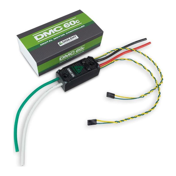
DMC60C Reference Manual
The DMC60C is the feature-packed, CAN-enabled successor to the DMC60. It is a powerful,
compact, FIRST Robotics Competition (FRC) approved motor controller designed for use with any
12-24V brushless DC motor. The DMC60C features an open loop PWM control mode, two internal
closed loop control modes (voltage compensation, current control), two external closed loop control
modes (position, velocity), and a follower control mode. These features are made available in
competition with an easy-to-use API, complete with examples, in C/C++, Java, and LabVIEW. The
DMC60C also features a web configuration utility that can be installed on any FRC configured
roboRIO. This configuration utility enables live configuration of several DMC60C parameters
including closed loop PID constants. This makes the DMC60C an ideal component in any robotics
application.
Advertisement
Table of Contents

Related Manuals for Digilent DMC60C


Summary of Contents for Digilent DMC60C
- Page 1 FIRST Robotics Competition (FRC) approved motor controller designed for use with any 12-24V brushless DC motor. The DMC60C features an open loop PWM control mode, two internal closed loop control modes (voltage compensation, current control), two external closed loop control modes (position, velocity), and a follower control mode.
-
Page 2: Specifications
Features Callout Feature Description CalloutFeature Description Input Ground (GND) Brake/Coast CAL Button Positive Input (V+) Positive Output (M+) Input Signal Cables (x2) 7 Output Ground (M-) Status LEDs (x4) Specifications 1 Electrical PARAMETER NOMINAL UNIT Input Voltage Continuous Current Surge Current (2 seconds) PWM Input Signal Pulse Width PWM Input Signal Period PWM Input Signal Throttle Dead Band... - Page 3 PWM Output Signal Frequency 2 Mechanical The DMC60C’s aluminum case is electrically isolated and may be mounted directly to a robot using zip-ties or #8-32 screws. The case may become hot after pro-longed use in high current applications. For optimum performance it is recommended that the DMC60C be mounted in a location that allows airflow over the top of the case and around both sides of the case.
-
Page 4: Functional Description
If the DMC60C output leads are not long enough to reach the motor then they may be extended. It is recommended that 12 AWG (or thicker) stranded wire be used and that the wires be soldered directly together. - Page 5 When a neutral pulse width is detected, the present Brake/Coast setting is applied to the output. The DMC60C expects the PWM Input Signal to have an input period between 2.9 and 100 milliseconds. The allows te update rate to be as high as 344 Hz or as low as 10 Hz.
- Page 6 Table 4.1 LED Patterns in PWM Operating Mode Servo Input Signal Applied LED State No Input Signal or Invalid Input Pulse Alternate between top (LED1 and LED2) and bottom (LED3 Width and LED4) LEDs being illuminated Red and Off. Neutral Input Pulse Width All 4 LEDs illuminated Orange.
-
Page 7: Input Signal Calibration
The Brake/Coast setting is stored in non-volatile memory and is re-stored automatically after power cycles. When the DMC60C is connected to a CAN bus the Brake/Coast setting may be overridden by the CAN control frame. When the Brake/Coast override is active the Brake/Coast CAL LED is overridden to display the setting specified by the CAN control frame. - Page 8 8 Input Voltage Monitoring and Under Voltage Protection The DMC60C continuously monitors the input voltage. If the input voltage falls below 5.75 Volts (+/- 2%) for 5 or more seconds, then the output duty cycle will be set to 0% and an under voltage fault is signaled.
-
Page 9: Fault Indicators
Present 10 Expansion Connector The DMC60C includes a 10-pin (2 x 5, 0.050” pitch) expansion port that allows sensors to be directly attached to the controller. Presently it supports direct attachment of limit switches and quadrature encoders. The figure below shows the pinout. Please note that any sensor attached to the expansion port should be powered through pin 1 (+3.3V) and/or pin 2 (+5V) and should not be powered by an... -
Page 10: Limit Switches
By default, both the forward and reverse limit switch inputs are enabled and configured to interface with normally open switches. When a limit switch is active the DMC60C will not allow the motor output to be driven in the associated direction. Any attempt to drive the output in the direction of an active limit switch will result in the neutral duty cycle being applied to the H-Bridge. - Page 11 Figure 11.1 Figure 11.2 Figure 11.3...
-
Page 12: Quadrature Encoder Input
A quadrature encoder may be attached to the Encoder A, Encoder B, and Encoder Index (optional) pins of the DMC60C expansion port. Please note that the encoder should be powered by the +3.3V or +5V pins of the expansion port, and that these pins should never be connected to each other. - Page 13 Encoder Index pin is ignored by the DMC60C. The DMC60C may also be configured to clear the position count based on the logic level of a signal applied to the Forward Limit or Reverse Limit pins of the expansion connector. By default, this functionality is disabled.
- Page 14 2. Hold the Brake / CAL button down. 3. While continuing to hold the button, apply power to the DMC60C. 4. Continue holding down the button until the top and bottom LEDs alternate quickly between Green and Off.
Need help?
Do you have a question about the DMC60C and is the answer not in the manual?
Questions and answers