
Related Manuals for ASROCK STX-1500


Summary of Contents for ASROCK STX-1500
- Page 1 STX-1500 User Manual Version 1.0 Published November 2020 Copyright©2020 ASRockInd INC. All rights reserved.
- Page 2 Version 1.0 Published November 2020 Copyright©2020 ASRockInd INC. All rights reserved. Copyright Notice: No part of this documentation may be reproduced, transcribed, transmitted, or translated in any language, in any form or by any means, except duplication of documentation by the purchaser for backup purpose, without written consent of ASRockInd Inc.
- Page 3 ® The terms HDMI and HDMI High-Definition Multimedia Interface, and the HDMI logo are trademarks or registered trademarks of HDMI Licensing LLC in the United States and other countries. CAUTION: RISK OF EXPLOSION IF BATTERY IS REPLACED BY AN INCORRECT TYPE. DISPOSE OF USED BATTERIES ACCORDING TO THE INSTRUCTIONS.
-
Page 4: Table Of Contents
Contents 1 Introduction ............5 1.1 Package Contents ............5 1.2 Specifications ..............6 1.3 Motherboard Layout ............8 1.4 I/O Panel ................ 10 2 Installation ............12 2.1 Screw Holes ..............12 2.2 Pre-installation Precautions ........... 12 2.3 Installation of Memory Modules (SO-DIMM) ....13 2.4 Expansion Slot ............... -
Page 5: Introduction
Chapter 1: Introduction Thank you for purchasing ASRockInd STX-1500 motherboard, a reliable mother- board produced under ASRockInd’s consistently stringent quality control. It delivers excellent performance with robust design conforming to ASRockInd’s commitment to quality and endurance. In this manual, chapter 1 and 2 contain introduction of the motherboard and step- by-step guide to the hardware installation. -
Page 6: Specifications
1.2 Specifications Form Dimensions Mini-STX (5.5-in x 5.8-in) Factor ® Intel Gen (Tiger Lake-UP3) Core Processors, up to 28W - STX-1500P (i7-1185G7E, 2.8GHz, 28W) Processor - STX-1500M (i5-1145G7E, 2.6GHz, 28W) System - STX-1500V (i3-1115G4E, 3.0GHz, 28W) Chipset BIOS AMI SPI 256 Mbit 1 x M.2 (Key E, 2230) with PCIe x1, USB 2.0 and CNVi for Wireless Expansion... - Page 7 HDMI 3 x HDMI 2.0a 1 x 2.5 Gigabit LAN Ethernet Rear I/O 1 x 1 Gigabit LAN 2 x USB 3.2 (Gen2), 2 x USB2.0 DC Jack 1 x USB 2.0 (1 x 2.54 pitch header) 1 x COM (RS-232) 1 x COM (RS-232/422/485) GPIO 4 x GPI, 4 x GPO...
-
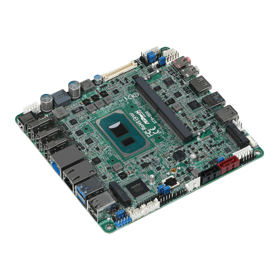
Page 8: Motherboard Layout
1.3 Motherboard Layout... - Page 9 1 : 4-pin DC-in PWR Connector (Input +12V~+28V) & UPS Module Power Output Connector 2 : LVDS Panel Connector 3 : BL1, BL2 4 : Backlight Power Connector (BLT_PWR1) 5 : Panel Power Select (LCD_VCC) (PNL_PWR1) 6 : Backlight Power Select (LCD_BLT_VCC) (BKT_PWR1) 7 : 3W Audio AMP Output Wafer 8 : SPDIF Header 9 : Front Panel Audio Header...
-
Page 10: I/O Panel
1.4 I/O Panel Front I/O: 1 : USB2.0 Port (USB2_3) 2 : USB3.2 Gen2 Port (USB3_2) 3 : HDMI Port (HDMI4) 4 : Audio Jack (Green - Line Out) 5 : Audio Jack (Pink - Mic In) Rear I/O: 1 : DC Jack (DC_JACK1) 2 : HDMI Port (HDMI1) 3 : HDMI Port (HDMI2) 4 : HDMI Port (HDMI3) - Page 11 ** There are two LED next to the LAN port. Please refer to the table below for the LAN port LED indications. LAN Port LED Indications ACT/LINK SPEED Activity/Link LED SPEED LED Status Description Status Description No Link 10Mbps connection Blinking Data Activity Orange 100Mbps connection...
-
Page 12: Installation
Chapter 2: Installation This is a Mini-STX form factor (5.5" x 5.8") motherboard. Before you install the motherboard, study the configuration of your chassis to ensure that the motherboard fits into it. Make sure to unplug the power cord before installing or removing the motherboard. -
Page 13: Installation Of Memory Modules (So-Dimm)
2.3 Installation of Memory Modules (SO-DIMM) This motherboard provides two 260-pin DDR4 (Double Data Rate 4) SO-DIMM slots. 1. It is not allowed to install a DDR, DDR2 or DDR3 memory module into a DDR4 slot; otherwise, this motherboard and SO-DIMM may be damaged. -
Page 14: Expansion Slot
2.4 Expansion Slots There are 2 M.2 sockets and 1 SIM socket on this motherboard. SIM socket: 1 x SIM socket connected to M.2 key B. M.2 slots: 1 x M.2 (M2_M1, Key M, 2242/2260/2280) with SATA3 and PCIe Gen4 x4 for SSD. -
Page 15: Jumpers Setup
2.5 Jumpers Setup The illustration shows how jumpers are setup. When the jumper cap is placed on pins, the jumper is “Short”. If no jumper cap is placed on pins, the jumper is “Open”. The illustration shows a 3-pin jumper whose pin1 and pin2 are “Short”... - Page 16 Backlight Power Select Use this to set up the backlight (LCD_BLT_VCC) power of the LVDS connector and the panel backlight power (5-pin BKT_PWR1) of BLT_PWM1. (see p.8 No. 6) 1-2: LCD_BLT_VCC: +5V 2-3: LCD_BLT_VCC: +12V 4-5: LCD_BLT_VCC: DC_IN Backlight Control Level (CON_LBKLT_CTL) 1-2: eDP Level 2-3: CH7511B Control (3-pin BLT_PWM1)
-
Page 17: Onboard Headers And Connectors
2.6 Onboard Headers and Connectors Onboard headers and connectors are NOT jumpers. Do NOT place jumper caps over these headers and connectors. Placing jumper caps over the headers and connectors will cause permanent damage of the motherboard! SATA3 Connectors These two Serial ATA3 (SATA3) connectors support (SATA3_0, SATA3_1: see p.8, No. - Page 18 HDLED (Hard Drive Activity LED): Connect to the hard drive activity LED on the chassis front panel. The LED is on when the hard drive is reading or writing data. The front panel design may differ by chassis. A front panel module mainly consists of power switch, reset switch, power LED, hard drive activity LED, speaker and etc.
- Page 19 Though this motherboard provides 4-Pin chassis fan (Quiet Fan) support, the 3-Pin chassis fan still can work successfully even without the fan speed control function. If you plan to connect the 3-Pin chassis fan to the chassis fan connector on this motherboard, please connect it to Pin 1-3. SPDIF Header (3-pin SPDIF1: see p.8, No.
- Page 20 COM1, 2 Headers (9-pin COM1, COM2: see p.8, No. 23) Signal Signal Signal Signal Signal Name Name Name Name Name DDCD# TTXD RRTS# RRI# RRXD DDTR# DDSR# CCTS# * This motherboard supports RS232/422/485 on COM1 port. Please refer to below table for the pin definition. In addition, COM1 port (RS232/422/485) can be adjusted in BIOS setup utility >...
- Page 21 SPI TPM Header (9-pin SPI_TPM1: see p.8, No. 19) Backlight Volume Control (7-pin BLT_VOL1) (see p.8 No. 13) Signal Signal Signal Signal Signal Signal Signal Name Name Name Name Name Name Name GPIO_ GPIO_ 5 BLT_DW BLT_UP PWRDN VOL_DW VOL_UP SATA Power Output Connector (4-pin SATA_PWR1) (see p.8 No.
-
Page 22: Summary Of Internal Power Sources
2.7 Summary of Internal Power Sources Onboard Source 12V2 DC-IN Max. overall Load SATA_PWR1 PNL_PWR1 BKT_PWR1 CHA_FAN1 JGPIO_PWR1... -
Page 23: Uefi Setup Utility
Chapter 3: UEFI SETUP UTILITY 3.1 Introduction This section explains how to use the UEFI SETUP UTILITY to configure your system. The UEFI chip on the motherboard stores the UEFI SETUP UTILITY. You may run the UEFI SETUP UTILITY when you start up the computer. Please press <F2>... -
Page 24: Navigation Keys
3.1.2 Navigation Keys Please check the following table for the function description of each navigation key. Navigation Key(s) Function Description Moves cursor left or right to select Screens Moves cursor up or down to select items + / - To change option for the selected items <Enter>... -
Page 25: Advanced Screen
3.3 Advanced Screen In this section, you may set the configurations for the following items: CPU Configu- ration, Chipset Configuration, Storage Configuration, Super IO Configuration, AMT Configuration, ACPI Configuration, USB Configuration and Trusted Computing. Setting wrong values in this section may cause the system to malfunction. -
Page 26: Cpu Configuration
3.3.1 CPU Configuration Intel Hyper Threading Technology Intel Hyper Threading Technology allows multiple threads to run on each core, so that the overall performance on threaded software is improved. Active Processor Cores Select the number of cores to enable in each processor package. CPU C States Support Enable CPU C States Support for power saving. - Page 27 Intel Turbo Boost Technology Intel Turbo Boost Technology enables the processor to run above its base operating frequency when the operating system requests the highest performance state. CPU Thermal Throttling You may select [Enabled] to enable CPU internal thermal control mechanism to keep the CPU from overheating.
-
Page 28: Chipset Configuration
3.3.2 Chipset Configuration VT-d ® ® Use this to enable or disable Intel VT-d technology (Intel Virtualization Technology for Directed I/O). The default value of this feature is [Disabled]. Share Memory Configure the size of memory that is allocated to the integrated graphics processor when the system boots up. - Page 29 Onboard LAN1 This allows you to enable or disable the Onboard LAN1 feature. Onboard LAN2 This allows you to enable or disable the Onboard LAN2 feature. Onboard HD Audio Select [Enabled] or [Disabled] for the onboard HD Audio feature. Deep Sleep Mobile platforms support Deep S4/S5 in DC only and desktop platforms support Deep S4/S5 in AC only.
-
Page 30: Storage Configuration
3.3.3 Storage Configuration SATA Controller(s) Use this item to enable or disable the SATA Controller feature. SATA Mode Selection Use this to select SATA mode. Configuration options: [IDE Mode], [AHCI Mode] and [Disabled]. The default value is [AHCI Mode]. AHCI (Advanced Host Controller Interface) supports NCQ and other new features that will improve SATA disk perfor- mance but IDE mode does not have these advantages. -
Page 31: Super Io Configuration
3.3.4 Super IO Configuration COM1 Use this to enable or disable COM1. Type Select Use this to select COM1 port type: [RS232], [RS422] or [RS485]. COM2 Use this to enable or disable COM2. WDT Timeout Reset This allows users to enable/disable the Watch Dog Timer timeout to reset system. -
Page 32: Amt Configuration
3.3.5 AMT Technology AMT BIOS Features Use this to enable or disable Intel(R) Active Management Technology BIOS Extension. The default is [Enabled]. ASF support Use this to enable or disable Alert Specification Format. The default is [En- abled]. USB Provisioning of AMT Use this to enable or disable AMT USB Provisioning. - Page 33 WatchDog Use this to enable or disable AMT WatchDog Timer. The default is [Dis- abled]. Activate Remote Assistance Process Trigger CIRA boot. The default is [Disabled]. PET Progress User can enable or disable PET Events progress to receive PET events or not.
-
Page 34: Acpi Configuration
3.3.6 ACPI Configuration Suspend to RAM Use this item to select whether to auto-detect or disable the Suspend-to- RAM feature. Select [Auto] will enable this feature if the OS supports it. Onboard LAN Power On Allow the system to be waked up by onboard LAN. RTC Alarm Power On Allow the system to be waked up by the real time clock alarm. -
Page 35: Usb Configuration
3.3.7 USB Configuration Legacy USB Support Use this option to select legacy support for USB devices. There are two configuration options: [Enabled] and [UEFI Setup Only]. The default value is [Enabled]. Please refer to below descriptions for the details of these two options: [Enabled] - Enables support for legacy USB. -
Page 36: Trusted Computing
3.3.8 Trusted Computing Security Device Support Enable or disable BIOS support for security device. -
Page 37: Hardware Health Event Monitoring Screen
3.4 Hardware Health Event Monitoring Screen In this section, it allows you to monitor the status of the hardware on your system, including the parameters of the CPU temperature, motherboard temperature, CPU fan speed, chassis fan speed, and the critical voltage. CHA_FAN1 Setting This allows you to set chassis fan 1’s speed. -
Page 38: Security Screen
3.5 Security Screen In this section, you may set, change or clear the supervisor/user password for the system. Supervisor Password Set or change the password for the administrator account. Only the ad- ministrator has authority to change the settings in the UEFI Setup Utility. Leave it blank and press enter to remove the password. -
Page 39: Boot Screen
3.6 Boot Screen In this section, it will display the available devices on your system for you to config- ure the boot settings and the boot priority. Boot From Onboard LAN Use this item to enable or disable the Boot From Onboard LAN feature. Setup Prompt Timeout This shows the number of seconds to wait for setup activation key. - Page 40 CSM (Compatibility Support Module) Enable to launch the Compatibility Support Module. Please do not disable unless you’re running a WHCK test. If you are using Windows 8 / 8.1 64- bit and all of your devices support UEFI, you may also disable CSM for faster boot speed.
-
Page 41: Exit Screen
3.7 Exit Screen Save Changes and Exit When you select this option, it will pop-out the following message, “Save configuration changes and exit setup?” Select [OK] to save the changes and exit the UEFI SETUP UTILITY. Discard Changes and Exit When you select this option, it will pop-out the following message, “Discard changes and exit setup?”... -
Page 42: Software Support
Chapter 4: Software Support 4.1 Install Operating System ® ® This motherboard supports Microsoft Windows operating systems: 10 64-bit. Be- cause motherboard settings and hardware options vary, use the setup procedures in this chapter for general reference only. Refer to your OS documentation for more information.
Need help?
Do you have a question about the STX-1500 and is the answer not in the manual?
Questions and answers