Sign In
Upload
Download
Table of Contents
Contents
Add to my manuals
Delete from my manuals
Share
URL of this page:
HTML Link:
Bookmark this page
Add
Manual will be automatically added to "My Manuals"
Print this page
×
Bookmark added
×
Added to my manuals
Manuals
Brands
Calorex Manuals
Dehumidifier
Variheat AA600
Owners & installation manual
Calorex Variheat AA600 Owners & Installation Manual
Hide thumbs
1
2
Table Of Contents
3
4
5
6
7
8
9
10
11
12
13
14
15
16
17
18
19
20
21
22
23
24
25
26
27
28
29
30
31
32
33
34
35
36
37
38
39
40
41
42
43
44
45
46
47
48
49
50
51
52
53
54
55
56
57
58
59
60
61
62
63
64
65
66
67
68
69
70
71
72
page
of
72
Go
/
72
Contents
Table of Contents
Bookmarks
Table of Contents
Table of Contents
Heath and Safety Warning
Features of the Variheat Range
How to Use the Variheat
Touchscreen User Interface
Data Entry
2 User Settings
Advanced Settings
Remote Access to the Variheat Touchscreen
3 Installation
Siting, Machine Location
Fresh Air and Exhaust Air
Plumbing Installation
Electrical Connections
Electrical Installation
Volt Free Terminals and Remote Access
Network Connection
Bms Connection (Building Management System)
Optional Remote Sensor Box
4 After Installation
Maintenance
Circuit Diagrams
5 Data Sheet
Lphw Heating Data - Variheat with Standard Air Heater
Lphw Heating Data - Variheat with Upgraded Air Heater (Where Model Number Includes +Ec Lphw)
6 Dimensions
7 Variheat Configurations
8 Warranty Conditions
Advertisement
Quick Links
1
How to Use the Variheat
2
Electrical Connections
3
Maintenance
4
Circuit Diagrams
5
Dimensions
Download this manual
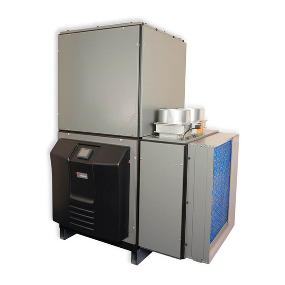
Variheat system
AA600/900/1200/1500
Owner installation manual (1002595 issue 5)
1
1002595 ISSUE 5 M172 VARIHEAT
Table of
Contents
Previous
Page
Next
Page
1
2
3
4
5
Advertisement
Table of Contents
Need help?
Do you have a question about the Variheat AA600 and is the answer not in the manual?
Ask a question
Questions and answers
Related Manuals for Calorex Variheat AA600
Dehumidifier Calorex Variheat AA900 Owners & Installation Manual
(72 pages)
Dehumidifier Calorex DH30A Installation Instructions Manual
(15 pages)
Dehumidifier Calorex vaporex DH30A Quick Start Manual
(3 pages)
Dehumidifier Calorex DH75AX Technical Manual
(26 pages)
Dehumidifier Calorex DH150 Owners & Installation Manual
(32 pages)
Dehumidifier Calorex DH44 Series Owners & Installation Manual
Wallhung/floorstanding dehumidifiers (100 pages)
Dehumidifier Calorex DH44 Technical Manual
Wallhung/ floorstanding dehumidifiers (36 pages)
Dehumidifier Calorex TTW33 Quick Start Manual
(3 pages)
Dehumidifier Calorex monitair DH44 Series Owners & Installation Manual
Wallhung/floorstanding dehumidifiers (20 pages)
This manual is also suitable for:
Variheat aa900
Variheat aa1200
Variheat aa1500
Table of Contents
Print
Rename the bookmark
Delete bookmark?
Delete from my manuals?
Login
Sign In
OR
Sign in with Facebook
Sign in with Google
Upload manual
Upload from disk
Upload from URL


Need help?
Do you have a question about the Variheat AA600 and is the answer not in the manual?
Questions and answers