Table of Contents
Advertisement
Table of contents
Introduction ...................................................................................................................................... 2
Hardware .......................................................................................................................................... 2
Objectives ...................................................................................................................................... 2
Filter turret .................................................................................................................................... 2
Laser lines ...................................................................................................................................... 3
Light Path ...................................................................................................................................... 3
Start up ............................................................................................................................................. 4
Sample mounting and viewing ......................................................................................................... 5
Software ........................................................................................................................................... 5
Sample viewing .............................................................................................................................. 6
Acquisition ..................................................................................................................................... 8
LSM Channel mode confocal setting ......................................................................................... 8
Configuration: ........................................................................................................................ 8
Single image acquisition ........................................................................................................ 12
Multidimensional acquisition ................................................................................................. 12
Shutting down ................................................................................................................................. 17
Instruction LSM700 2017-12-07.docx 2017-12-19
Confocal LSM 700
Advertisement
Table of Contents

Related Manuals for Zeiss LSM 700


Summary of Contents for Zeiss LSM 700
-
Page 1: Table Of Contents
Instruction LSM700 2017‐12‐07.docx 2017‐12‐19 Confocal LSM 700 Table of contents Introduction ............................2 Hardware ............................2 Objectives ............................2 Filter turret ............................ 2 Laser lines ............................3 Light Path ............................3 Start up ............................. 4 Sample mounting and viewing ......................5 Software ............................5 Sample viewing ..........................6 Acquisition ............................. 8 LSM Channel mode confocal setting .................. -
Page 2: Introduction
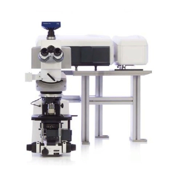
Introduction The Zeiss LSM 700 is equipped with 4 laser lines and can detect up to four color signals at frame rates approaching 5 frames per second at 512 x 512 pixels. Efficient separation of the fluorescence signals by selective laser excitation coupled to efficient splitting of the emission using the variable secondary dichroic (VSD) beamsplitter prevents crosstalk and enables spectral imaging as well as linear unmixing of highly overlapping fluorophores. Among the advanced features of the VSD beamsplitter is that all portions of the emission spectrum are utilized for determining each spectral data point. Hardware The microscope: The LSM 700 is attached to an upright microscope (Axio Imager Z2). Objectives Working Parfocal Position Objective lens Magnification NA coverslip Immersion distance length 1 W Plan 45 mm X40 0 2.5 mm Water dipping Apochromat 2 EC Plan 45 mm 0.3 0.17 mm 5.2 mm Air Neofluar 3 Plan ... -
Page 3: Laser Lines
Laser lines Laser Line Solid state 5mW 639 Solid state 10mW 555 Solid state 10mW 488 Solid state 5mW 405 Light Path 1. The lasers come aligned from the manufacturer, all 4 lasers are attached to an optic cable and enter the confocal scan head. (1) 2. The laser lines are reflected by the main dichroic mirror (beamsplitter). (4). 3. The 2 Galvanometric mirrors scanthe sample. (3). 4. The return emission wavelength passes through the main dichroic mirror (4). 5. The emission passes through the pinhole aperture and the out of focus light is eliminated.(5) 6. The variable secondary dichroic beamsplitter (VSD) is coated with a variable coating that between 420nm ‐ 630nm, according to the position of light incidence determines the cutoff below which wavelength the light will pass to PMT1 and above this wavelength it will be reflected towards PMT2.(6) 7. Before the detection an emission filter can be inserted from the filter wheel before the PMT, only longpass (LP)/shortpass (SP) filters are available. (9) 8. The light is detected in one of the two PMT detectors‐ PMT 1 for SP emission wavelength, PMT 1 for LP emission wavelength.(7,8) p. 3 ... -
Page 4: Start Up
Start up Turn on the system in the following order: ‐ In the power strips turn on switches 1 2. ‐ Turn on the stage controller (3) ‐ Rotate (clockwise) the silver key in the lasers electronic unit(4) ‐ Turn on the computer and log in User name: multilabs Password: 123456 ‐ Turn on the metalhalide lamp (6) 6 p. 4 ... -
Page 5: Sample Mounting And Viewing
Sample mounting and viewing Insert the slide or dish to the stage holder. Push in the Light switch between the ocular and the confocal. Via the touch pad: 1. Choose the preferred objective 2. Choose the proper filter set and open the TL\RL shutter: Filter set Software ‐ Log into BookitLab and activate your reservation to start Black Zen 2.3 ‐ To acquire images click Start System p. 5 ... -
Page 6: Sample Viewing
Sample viewing In the Locate tab choose the preferred objective filter set and open the illumination shutter RL\TL Set the Transmitted light (In case the TL is needed) Click the transmitted light lamp icon, click ON and set desired brightness (or via the microscope). Set the filter turret position to DIC and the condenser below the stage to I, II or III according to the objective lens (see objective lens info on touchpad). If you are acquiring transmitted channel set up Kohler illumination: Bring the sample into focus. Close the field stop using the motorized aperture button (F) located at the right of the microscope until you can see at least one edge Adjust the condenser height until the edges of the diaphragm image are crisp. Center the diaphragm image using the two centering screws. Open the field diaphragm, just until the image fills the field of view. p. 6 ... - Page 7 2, 5 3 p. 7 ...
-
Page 8: Acquisition
Acquisition LSM Channel mode confocal setting In the software go to the Acquisition main tool tab Pull out the Light switch between the ocular and the confocal. Configuration: It is highly recommended to seek BCF staff’s advice for new fluorophores (exact name) or new combinations. Choose one: Load a saved configuration from the Experiment Manager Reuse settings of an image: open an image and below the image click Reuse New setup: click , choose the desired dyes from the list, choose the scanning method and click Apply ... - Page 9 Select show all tool and open the Imaging set up tab Note: make sure that the chosen configuration is correct and suits the fluorophores; make changes if needed it is highly recommended to check all dyes spectrums in a spectra viewer ThermoFisher Chroma 6 3.1 1. Laser lines 2. Main dichroic mirror 3. PMTs: PMT1 and PMT2 4. Variable secondary dichroic beamsplitter (VSD). 5. Emission Filter selection 6. Emission spectrum with Graphic representation of the laser line, the position of the VSD and emission filter. 7. Transmitted light PMT‐ a transmitted light image (non confocal) can be added to the confocal image (it recommended to add to the longest wavelength track). p. 9 ...
-
Page 10: Acquisition & Parameter Setting
Acquisition & parameter setting Pull out the lightpath switch between the ocular and the confocal Parameter setting Open the Acquisition mode tab Scan mode: frame (in most cases); line scan mode can be useful for physiology experiments. Frame size: 512X512 Speed: 8 Averaging: Method: mean (in most cases): in low signal with low noise Sum method may be useful Number: 1 Mode: frame for fixative sample, for live cells and in case of unstable dye line mode will be more suitable Bit Depth: defined the dynamic range of the image, choose 8bit\12 bit according to the biological question. Direction: ‐‐‐‐> (more precise) Scan area: slight nudge, zoom and rotation ... - Page 11 Open the Channels tab Check and select only the shortest wavelength track and click the 1AU button Start scan in continuous mode Check the Range indicator (below the image container in the Dimensions tab). Set your image parameters to achieve image without saturation (saturation=red pixels in the image) and the correct black level (black= blue pixels in the image) o Set the PMT gain to 550‐600. o Set the Laser % ‐ it is recommended to use the lowest % as possible and to increase gain (master). o In case of low signal with high laser % and high gain you can add digital gain (up to 2). o Set the offset level until you reach the PMT threshold (blue pixel will appear in the image while scanning in range indicator mode). Stop the scan Select another track; set its pinhole to the same μm section as the first track and set its parameters and so on Stop the scan p. 11 ...
-
Page 12: Single Image Acquisition
Single image acquisition In the Acquisition Mode tab select the preferred zoom (alternatively you can easily position the cropping frame to zoom in via the crop tool below the image in the Dimensions tab) Scan one frame to check position. Check all tracks in the Channel tab, In the Acquisition Mode tab click to set the frame size. Set scanning speed to 6 Set averaging number to 2‐4 (according to the SNR) Press Snap in the start buttons Save the image: press in the Images and Documents tab (right hand side of the window) and save in the directory: D:\Users data\PI name\MM‐YYYY\User name\YYYY‐MM‐DD Multidimensional acquisition Z stack In the Multidimensional Acquisition options below the start buttons check Z stack; a new tab (Z‐stack) will appear under the Multidimensional Acquisition Section. Set the interval: press Smallest for the system recommendation (Nyquist criterion) With one channel checked and In the Acquisition mode tab: Frame size 512X512 Scanning speed 8 ... - Page 13 Start scan in continuous mode Define the signal boundaries by moving the focus wheels and pressing Set First in one boundary and Set Last in the second boundary. With all channels checked, in the Acquisition mode tab: Frame size Press optimal Scanning speed 7 Averaging number 2‐4 Press Save the Image Note: there are more advanced Z stack options in this tab such as brightness correction over z. Time series In the Multidimensional Acquisition options check Time series; a new tab (Time Series) will appear under the Multidimensional Acquisition Section. Define number of cycles and the interval Note: in case of live cell imaging avoid high laser intensity In the Acquisition Mode tab: Frame size Press optimal In case of big frame size with long frame scan time it recommended to increase the zoom and set a new frame size with less pixels by pressing optimal again. Scanning speed: 7‐8 Averaging number 1‐2 ...
- Page 14 Tile In the Multidimensional Acquisition options check Tile scan; a new tab (Tile Scan) will appear under the Multidimensional Acquisition Section. Define the number of tiles Define the overlap % ‐ recommended is 8%‐15% Calculate slide rotation: In the main menu choose Macro Tile scan rotation In the popup window press Calibrate and wait until the process is finished (the rotation angle will be exported to the tile scan tab) then press close. Note: Online stitching is not a recommended option, the process can be configured in the processing main tool tab. In the Acquisition mode tab: Frame size: Press optimal Zoom: It is recommended to set the zoom above 1.2 Scanning speed: 7 Averaging number: 2 Press Save the Image Stitching: In the Processing main tool tab Stitch select your input image press Apply. In case of uneven illumination the stitching process can be done with more options in the ZEN blue software. ...
- Page 15 Repeat bleach after number of scans The amount of iterations The laser and its intensity More setting can be defined in the bleaching dialog. Define one or more ROIs: After a single scan in the Regions tab choose one of the ROI tools and draw on the acquired image; the dimensions can also be set manually in the Width/Height textboxes. Define which process will be performed in the ROI – Acquisition/Bleach/Analysis. Define Time series: In the Acquisition mode tab: Frame size Press optimal Scanning speed 7 or more Averaging number 1‐2 Press p. 15 ...
- Page 16 Save the image The intensity data from the ROI can be viewed in the ROI mean tab in the image window Note: The region can be defined in other types of experiments with or without time lapse and can also be used as a tool of zooming in by checking Fit Frame size to bounding rectangle of regions. Positions A positions list can be added to a multidimensional experiment in which all of the settings will be acquired (channel, acquisition mode, Z stack, tile, time series). The Positions tab can be a useful tool in managing a large tile and for quick slide scanning (via the ocular) with low magnification before moving to high magnification with small field of view. Add a position by pressing Positions below the image container and clicking on the image container that was just acquired at the current stage position Check Positions at the Multidimensional Acquisition options. At the Positions tab move to a position in the list by selecting and pressing Move to A position can also be added by pressing Add in the Positions tab Note: If you use the positions list only to locate saved positions uncheck Positions from the Multidimensional Acquisition options before pressing Start Experiment, otherwise your settings will be acquired at every position in the list. Note you can use multiple options in the multidimensional scanning for example Z stack & tile Time series, bleaching, ROI & Z stack and positions. p. 16 ...
-
Page 17: Shutting Down
Shutting down ‐ Make sure all the data is saved. The data will be automatically saved to the server during the night. PLEASE DO NOT USE ANY USB FLASH DRIVE on this computer. ‐ Clean any oil immersion objectives you used with lens paper and petroleum ether, twice. ‐ Close the ZEN software ‐ Log off from your account in the BookItlab window ‐ Check if another user has a reservation; if yes verify his/her arrival. If you are the last user for the day or the next reservation is in two hours or later, continue with system shutdown. ‐ Turn off the metalhalide lamp (6) ‐ Turn off the computer (5) only on weekends ‐ Turn off the laser electronic unit (4) ‐ Turn off the stage controller (3) ‐ Turn off switches 2 1 In the switch box ‐ Cover the microscope p. 17 ...
Need help?
Do you have a question about the LSM 700 and is the answer not in the manual?
Questions and answers