
Subscribe to Our Youtube Channel
Related Manuals for Ewellix CPMT


Summary of Contents for Ewellix CPMT
- Page 1 I N STA L L AT I O N, O P ER AT I O N AN D MA I NT EN A N C E M AN UA L CPMT Telescopic pillar Feature 1 max 2 lines Feature 2...
-
Page 3: Table Of Contents
Contents 1.0 General information ............4 7.0 Operation ..............23 1.1 Information in this manual ..........4 7.1 Safety ................23 1.2 Explanation of symbols and signal words ......4 7.2 Turn on ................23 7.3 Turn off ................23 1.3 Limitation of liability ............5 1.4 Copyright .................5 7.4 Actions before use ............23 1.5 Spare parts ..............5 7.5 Actions during operation .......... -
Page 4: General Information
C P M T 1.0 General information 1.1 Information in this DANGER Indicates a dangerous situation, which manual will lead to death or serious personal injury, if the precautionary measures are This manual provides important information on how to work ignored. -
Page 5: Limitation Of Liability
Where the telescopic pillar has been customized by Ewellix, contained in the Ewellix sales contract that governs this the actual product delivered may be different from what is sale. described in this manual. In this case, ask Ewellix for any ad- ditional instructions or safety precautions relevant to this 1.7 Customer service product. -
Page 6: Safety
2.1.1.1 Product service life NOTE The telescopic pillar CPMT is designed for a service life of Any unauthorized use of the device can cause personal injury 10 years in a typical medical procedure equipment and property damage. Always adhere to the instructions given in application. -
Page 7: Responsibility Of The Owner And Processor
2 .0 S afe t y 2.2 Responsibility of the 2.3 Personnel owner and processor requirements The device is designed for use in commercial applications WARNING by its owner or processor. Improper installation, operation and maintenance can result in The processor is the contracting partner of the reseller or serious injury, death or property damage. -
Page 8: Specific Dangers
In the event of a malfunction, the device cannot extend or retract. Protect CPMT against an unauthorised restart If required by the application, a separate provision for pa- Pull the power-line plug of the control unit attached to the tient release must be installed, to allow safe release of the CPMT, out of the power outlet. -
Page 9: Modifications Of Device
Class B Harmonic emissions Class A The telescopic pillar CPMT is suitable for use in all establishments, including IEC 61000-3-2 domestic establishments and those directly connected to the public low- voltage power supply network that supplies buildings used for domestic Voltage fluctuations/ flicker ... - Page 10 5 cycles for 5 cycles mains interruptions, it is recommended 70% U1 70% U1 that telescopic pillar CPMT is powered (30% dip in U1) (30% dip in U1) from an uninterruptible power supply for 25 cycles for 25 cycles or a battery.
- Page 11 CPMT (Table 6 – IEC 60601-1-2) The telescopic pillar CPMT is intended for use in an electromagnetic environment in which radiated RF disturbances are controlled. The customer or user of the telescopic pillar CPMT can help prevent electromagnetic interference by maintaining a minimum distance between portable and mobile RF communications equipment (transmitters) and the telescopic pillar CPMT as recommended below, according to the maximum output power of the communications equipment.
-
Page 12: Technical Data
C P M T 3.0 Technical data Fig. 2 NOTE The technical data (dimension, weight, output, connection details etc.) can be found in the appendix. 3.1 Ambient conditions Operation • Indoor use only at: Operation • Ambient temperature +10 to +40 °C. • ... -
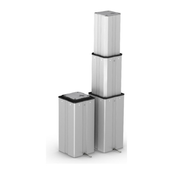
Page 13: Structure And Function
Areas of force distribution a1. Outer tube base plate 4.2 Brief description a2. Motor cable The functional principle of the telescopic pillar CPMT is a3. Outer tube based on a push or pull force for the movement of centric a4. Middle tube and eccentric loads. - Page 14 The inner tube is the tube with the smallest outside dimen- The stroke is limited by the integrated end limit switches that cut the power to the DC gear motor. If the CPMT moves be- sions. The CPMT pillar can be mounted in any orientation to...
-
Page 15: Requirements For Third Party Control Units (Mandatory In Medical Applications)
It is strongly recommended to use original Ewellix controls for The telescopic pillar is connected to the control unit via the the operation of the CPMT pillar. If third party controls are used, DIN-8 plug or the flying leads cable. there must be good documented evidence that the requirements Connected load is 24 V–30 V DC and up to 12 A according... -
Page 16: Operating Elements
C P M T Fig. 6 Stroke length The available stroke length for CPMT is from 300 mm to 600 Mechanical connections mm in 10 mm steps for retracted length ‘stroke/2 + 240 mm’, and from 400 mm to 600 mm in 10 mm steps for retracted length ‘stroke/2 + 120 mm’... -
Page 17: Transport, Packaging And Storage
• Do not remove the telescopic pillar CPMT from its packaging until 5.4 Packaging just before installation. • Note storage requirements for return transport of the device to the manufacturer (⮑ Storage, page 18) -
Page 18: Storage
C P M T 5.5 Storage Pack the device in its original packaging for storage • Do not store outside. • Dry and dust-free storage. • Keep away from any aggressive media. • Protect from UV radiation. • Avoid mechanical vibrations. • ... -
Page 19: Installation And First Operation
6 .0 I n s t a l l a ti o n a n d f i r s t o p e r a ti o n 6.0 Installation and first operation 6.1 Installation location Authorized personnel • The installation and first start of operation may only be • ... -
Page 20: Installation
Before connecting the telescopic pillar CPMT to a control unit, ensure that: • the telescopic pillar CPMT is attached to the metal plates 6.3.1 Installation overview of the application on both sides The telescopic pillar CPMT can be mounted to the application • ... -
Page 21: Connection To The Control Unit
Therefore: • Use only the auxiliary products listed by the manufacturer. All control units not approved by Ewellix for the CPMT pillar 3. Insert DIN-8 plug (3) into the connecting socket (1) of the are treated as third party controls. For further details regard- control unit. -
Page 22: Connection To Operating Element
C P M T 6.5 Connection to operating element NOTE Operational conditions are not displayed on CPMT telescopic pillars. However, this feature is mandatory in medical applications and must be present on the control unit being used. 6.6 Connection to power... -
Page 23: Operation
Static and dynamic overload can lead to damage and failure of appendix. the device. Therefore: • Electrical supply secured and the telescopic pillar CPMT • Do not exceed maximum permissible performance specifications securely connected to a control unit. for the device (⮑ Data sheets in the Appendix, page 31). • Operating device connected to the control unit. -
Page 24: Actions During Operation
5. Keep access paths open for rescue vehicles. 6. Based on severity of emergency, notify the authorities if The CPMT moves until the button is released or the end po- necessary. sitions are reached. When the end position is reached, an 7. -
Page 25: Maintenance
8 .0 M a i n te n a n c e 8.0 Maintenance Personnel • The maintenance work described here can be performed by the operator unless otherwise indicated. • Some maintenance tasks should only be carried out by specially trained, qualified personnel, or exclusively by the ... -
Page 26: Maintenance Plan
C P M T 8.1 Maintenance plan Maintenance tasks that are required for optimal and trou- ble-free operation are described in the sections below. If increased wear is detected during regular inspections, shorten the required maintenance intervals according to the actual indications of wear. -
Page 27: Measures Following Completed Maintenance
8 .0 M a i n te n a n c e Complete the following entries in the service log: 8.2.4 Visual check of external condition • Name of the executing body (company, department) To be performed by qualified personnel • Names of the staff on duty 1. Separate the device from the energy supply. • ... -
Page 28: Malfunctions
C P M T 9.0 Malfunctions This chapter describes potential causes of equipment mal- Actions during malfunctions function and the work required to restore operation. In the 1. In the event of a malfunction that may present an imme- event of more frequent malfunctions, shorten the mainte- diate danger to persons or assets, turn off the telescopic ... -
Page 29: Malfunction Table
Ensure that the load of the pillar is in the optimal Qualified personnel during movement range (no over- or underload) as defined in the technical specification Wear or failure in the mechanical brake Contact Ewellix service Qualified personnel 9.2 Start of operation after malfunction repair To restart device following repair of the malfunction, perform... -
Page 30: Dismantling
• Contact the manufacturer if you have any questions or concerns. 10.1 Dismantling The telescopic pillar CPMT is to be removed from service in the following sequence: 1. De-energize the CPMT by unplugging the cable from the external control unit. -
Page 31: Appendix
The equipment and operating data can be found in the cur- rent data sheet. Data sheet for Ewellix Telescopic pillar for medical proce- dure equipment – Series CPMT (PUB NUM TC-08027-EN- April 2020) Current data sheets are available on the Ewellix website (see ewellix.com). Technical data Unit CPMT1-1S... -
Page 32: Plans And Diagrams
C P M T 11.2 Plans and diagrams To view the plans and diagrams, please contact Ewellix. Further information can be found in the data sheet. Current data sheets are available on the Ewellix website (see ewellix.com). Connection diagram 24–30 V DC... - Page 33 11 .0 A p p e n d i x Offset load diagram Speed-load diagram CPMT1-1S, -2S CPMT1-1 Load [N] Speed [mm/s] 7 000 6 000 5 000 overload 4 000 3 000 ideal 2 000 1 000 underload 1 000 2 000 3 000 4 000...
-
Page 34: Approved Accessories
C P M T Dimensional drawing Fig. 12 Ø11 Ø10,5 Ø20 Ø22 Ø15 4x M10/30 40 Nm 4× M10/30 40 Nm Max. Length 2 300 mm Ø22 Ø10,5 Ø11 11.3 Approved accessories Accessories Description Part number Control Unit SCU (3 or 6 ports) SCUXX-003XXX-000 Control Unit VCU (3 or 5 ports) VCUXX-003XX0-000... - Page 36 © Ewellix All contents of this publication are the property of Ewellix, and may not be reproduced or given to third parties (even extracts) without permission. Although great care has been taken in the production of this catalog, Ewellix does not take any responsibility for damage or other loss resulting from omissions or typographical errors.
Need help?
Do you have a question about the CPMT and is the answer not in the manual?
Questions and answers