
Related Manuals for WEG PSRW


Summary of Contents for WEG PSRW
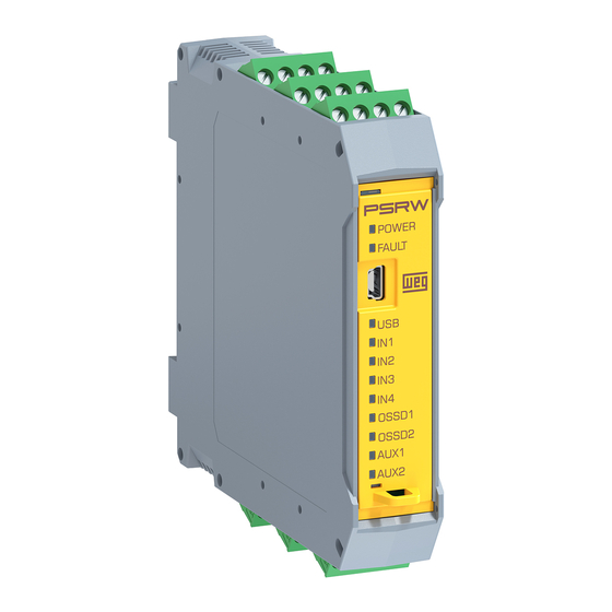
- Page 1 Motors | Automation | Energy | Transmission & Distribution | Coatings PSRW Programmable Safety Relay WEG User's Manual...
- Page 3 User’s Manual Series: PSRW Language: English Document: 10005909449 / 01 Publication Date: 05/2019...
- Page 4 Summary of Reviews The information below describes the revisions made to this manual. Version Review Description First edition New review...
-
Page 5: Table Of Contents
3.4 ELECTRICAL CONNECTIONS ................3-2 3.5 INSTRUCTION TO CABLE AND TERMINALS ............ 3-3 3.6 USB INPUT......................3-3 3.7 CONNECTION EXAMPLE OF PSRW TO MACHINE CONTROL SYSTEM ..3-4 3.8 CHECK LIST AFTER INSTALLATION ..............3-4 4 OPERATION DIAGRAM ................4-1 5 SIGNALS .................... - Page 6 9.5.2 Logic and delay timer configuration ............9-13 9.5.3 OSSD output and auxiliary output configuration ........9-14 9.6 TRANSFERRING CONFIGURATIONS .............. 9-15 9.7 RETRIEVING CONFIGURATIONS FROM PSRW ..........9-19 9.7.1 Saving configurations on PC ..............9-20 10 PRODUCT USE WITH SAFETY ............10-1 11 MODIFICATIONS .................
-
Page 7: Introduction
Introduction 1 INTRODUCTION This manual contains the instructions for the correct use of the PSRW device and safety information. System description. „ Method of Installation. „ Connections. „ Inputs / outputs. „ Troubleshoot. „ Use of the configurator tool. „... -
Page 8: Abbreviations
PL: performance level. CAT: category. ESPE: electrosensitive safety protection device. EDM: external device monitoring. WPS: WEG Programming Suite. 1.3 APPLICABLE STANDARDS PSRW complies with the following European Directives: 2006/42/UE “Machinery Directive”. „ 2004/108/UE “Electromagnetic Compatibility Directive”. „ 2006/95/UE “Low Voltage Directive”. - Page 9 Electromagnetic compatibility (EMC) – Part 6-7: Generic standards – Immunity requirements for equipment IEC61000-6-7 intended to perform functions in a safety-related system (functional safety) in industrial locations IEC 61131-2 Programmable controllers – Part 2: Equipment requirements and tests PSRW | 1-3...
- Page 10 Introduction 1-4 | PSRW...
- Page 11 Description 2 DESCRIPTION The PSRW is a configurable safety relay that can be programmed via WPS graphical interface. It has 4 (four) dual-channel safety inputs and 2 (two) OSSDs (dual-channel safety outputs) with configurable (manual/automatic) individual reset. PSRW is capable of monitoring the following safety sensors and components: Safety Light curtain.
-
Page 12: Description
Description 2-2 | PSRW... -
Page 13: Mounting
Mounting 3 MOUNTING 3.1 MECHANICAL FIXING The PSRW adopt a 35mm DIN rail. To proceed the fixation use the follow sequence: 1º step, fitting on rail. „ 2º step, spring action. „ 3º step, lock. „ Figure 3.1: DIN rail 35 mm mounting 3.2 OVERVIEW... -
Page 14: Calculation Of Safety Distance Of An Espe Connected To Psrw
PSRW response time + ESPE response time + response time of the machine. 3.4 ELECTRICAL CONNECTIONS The PSRW is provided with removable of terminal blocks for the electrical connections and has 6 terminal blocks with 4 pins each one: Table 3.1: Terminals of PSRW... -
Page 15: Instruction To Cable And Terminals
The same voltage reference (0 Vdc) must be used for all system components. 3.6 USB INPUT The PSRW includes a USB 2.0 connector for connection to a personal computer and access the configurator tool WPS manual available for download on the website: www.weg.net. -
Page 16: Connection Example Of Psrw To Machine Control System
Figure 3.3: Connection example 3.8 CHECK LIST AFTER INSTALLATION The PSRW is able to detect the internal faults. Anyway to assure the correct operation, the user must perform the following checks at start up and at least every one year: Perform a complete system test. -
Page 17: Operation Diagram
Operation Diagram 4 OPERATION DIAGRAM Fixing to DIN Rail Electrical connections PSRW to external components Connect to PC by USB Port Start system operation Setting parameters by software configuration tool Complete test on the machine and configuration valid for the application? - Page 18 Operation Diagram 4-2 | PSRW...
-
Page 19: Signals
5 SIGNALS 5.1 DIGITAL INPUTS The PSRW has four (4) dual-channel safety inputs that can take up to three (3) different configurations, being possible to individually configure contact filter and reset options. The inputs are identified by the name INx_y, where ‘x’... -
Page 20: Input Type: Simultaneity Control
Tep = time between pulses Figure 5.1: Example of test pulses For the PSRW to identify the pulses as test pulses, ‘Tp’ cannot be longer than 1 millisecond, and ‘Tep’ cannot be longer than 50 milliseconds. For further information, see Chapter 8 CONNECTION EXAMPLES on page 8-1. -
Page 21: Reset
For automatic inputs, the + Vdc level must be maintained. 5.3 RESET The RST_1 and RST_2 allows the PSRW to verify an EDM (External Device Monitoring) feedback signal (series of contacts) from the external contactors, and to monitor Manual/Automatic operation. -
Page 22: Test Outputs
To monitor the digital inputs configured as contact, it is necessary to use the test outputs (TEST_A and TEST_B) generated by the PSRW. The PSRW has two test output channels that must be connected to their respective input channel (channel A to channel A/channel B to channel B) for the correct operation of the input. - Page 23 (a) Manual Rising Edge (b) Manual Falling Edge (c) Time Pulse td = Time to switch on (5 ms maximum) tm = Time to monitored reset 50 ms < tm < 3 s Figure 5.5: (a) to (c) OSSD operation PSRW | 5-5...
- Page 24 Signals 5-6 | PSRW...
-
Page 25: Technical Specification
USB 2.0 – Max length of cable: 3 m 6.3 ENCLOSURE Housing with 6 pluggable blocks of 4 terminals each Description and locking latch mounting in cover front Material Polyamide Class protection IP20 Dimension (H x L x D) 108 x 22.5 x 114.5 (mm) PSRW | 6-1... -
Page 26: Mechanical Dimensions
Technical Specification 6.4 MECHANICAL DIMENSIONS 114.5 22.5 Figure 6.1: Mechanical dimensions 6-2 | PSRW... -
Page 27: Diagnosis
INPUT [1,4] No active input Over current █ input Input short circuit Yellow Auxiliary output Auxiliary output AUX [1,2] █ Under voltage Green OSSD OSSD OSSD [1,2] Over current █ output on output off Output short circuit PSRW | 7-1... - Page 28 Diagnosis 7-2 | PSRW...
-
Page 29: Connection Examples
8.1 EMERGENCY STOP CONNECTION EXAMPLE PSRW 8.2 TWO HANDS CONTROL CONNECTION EXAMPLE To connect a two hands control is necessary use two double channel inputs and it can be IN1-IN2 or IN3-IN4 and connect according to examples below. PSRW PSRW | 8-1... -
Page 30: Safety Sensor Connection Example
Connection Examples 8.3 SAFETY SENSOR CONNECTION EXAMPLE PSRW 8.4 LIGHT CURTAIN CONNECTION EXAMPLE Emitter Receiver OSSD_1 OSSD_2 PSRW 8-2 | PSRW... -
Page 31: Reset Inputs
Reset manual without EDM Reset manual with EDM To operate in reset automatic the input must be connected to 24 Vdc. + 24 Vdc + 24 Vdc PSRW PSRW Reset automatic without EDM Reset automatic with EDM PSRW | 8-3... -
Page 32: Auxiliary Output Connection
+ 24 Vdc + 24 Vdc PSRW PSRW Reset manual/automatic with EDM Reset manual/automatic without EDM 8.6 AUXILIARY OUTPUT CONNECTION AUXn PSRW ATTENTION! Check if the current consumption from load not exceed the maximum allowed (100 mA). 8-4 | PSRW... -
Page 33: Ossd Output Connection
Connection Examples 8.7 OSSD OUTPUT CONNECTION OUTn_A OUTn_B PSRW ATTENTION! Check if the sum of all loads of OSSD will not exceed the maximum allowed (2 A). PSRW | 8-5... - Page 34 Connection Examples 8-6 | PSRW...
-
Page 35: Programming With Wps
Programming With WPS 9 PROGRAMMING WITH WPS The PSRW is configured using software WPS (WEG Programming Suite). This software is already used to configure other products from WEG. This software available for download on the website: www.weg.net. The WPS uses a versatile graphic interface to establish the connections between the various components, as described below. -
Page 36: Application Set Up
9.2.1 Menu When WPS is launched, a welcome screen will be displayed. There are four options on it: New configuration: Used to create a new configuration for PSRW. Open Configuration: Used to open an existing configuration save on the computer. -
Page 37: Creating A Project
When selecting the option new configuration, a popup window will be displayed asking for a configuration name (also called project name), file path and a resource name. Type these data and click on “Next”. The next step is to setup the communication. In the combo-box “Preset” on Device” area, choose PSRW among other devices. - Page 38 Programming With WPS The communication parameters are loaded automatically, by this way, no further setup are needed except the COM port if PSRW was connected to the PC (see Section 9.3 SETTING UP COMMUNICATION on page 9-7). After that, click on “Next”.
- Page 39 Programming With WPS After that, click on “Finish”. On this moment, the created Project with the PSRW Resource appears in the configuration tab. PSRW | 9-5...
- Page 40 PSRWs, it can add a new Resource on the Project tree by right clicking on the Project and then clicking on “New Resource”. If you do that and follow the previous steps to create a Resource, it will be possible to observe the Resource under the Project tree: 9-6 | PSRW...
-
Page 41: Setting Up Communication
Programming With WPS 9.3 SETTING UP COMMUNICATION To be possible to read and configure PSRW, it is necessary to setup its communication with the PC. To do so, connect PSRW to the PC and follow the steps bellow: a. Check if the resource elected to communicate with PSRW is the main resource. - Page 42 Programming With WPS b. Test the communication. Right click on Resource and click on “Properties”. „ Choose the COM port in the list on combo-box “Porta”. It is likely the port number will be the higer number. „ 9-8 | PSRW...
- Page 43 COM port number and try again. Click on “OK”. „ c. Click on “Connect Device” Click on “Connect Device” toggle-button. Observe that it become selected and the status bar now contains „ a communication address. This means that WPS is recognizing PSRW PSRW | 9-9...
-
Page 44: Wizards
Programming With WPS 9.4 WIZARDS PSRW is configured through Wizards wizard Configurator and Wizard Monitor. In the first one, it is possible to: Design a configuration through component blocks. „ Print and transfer a configuration. „ Read configurations from PSRW. -
Page 45: Wizard Monitor
PSRW_Monitor Buttons Configuration viewer area: area where is possible to view configurations from PSRW. A more detailed explanation will be given in the following sections. Wizard Monitor Buttons: displays commands for zoom in/out , validate configurations on physical... -
Page 46: Configuring The Inputs
The component block used to configure the inputs is described below. Input name Input type: it selects Physical terminal what kind of device will be names – same connected on PSRW input. names present in PSWR label. Reset dependent: It defines whether the input depends on a manual reset or is automatic. -
Page 47: Logic And Delay Timer Configuration
Delay setup The logic block has 4 combo-box with option “Input 1”, “Input 2”, “Input 3”, “Input 4”and “Not used”. When an Input “n” is selected, the WPS will connect the input to logic block. PSRW | 9-13... -
Page 48: Ossd Output And Auxiliary Output Configuration
After set the inputs, logic block and delay time, the reset must be set according the options “Automatic”, “Rising Edge”, “Falling Edge” or “Rising and Falling Edge” (Time Pulse). To active the manual reset options in necessary set the flag “reset dependent” at input block. 9-14 | PSRW... -
Page 49: Transferring Configurations
Programming With WPS 9.6 TRANSFERRING CONFIGURATIONS The process of transfer a configuration to PSRW is: Connect physically PSRW to the PC. „ Open WPS and Open/Create a PSRW Resource (see Item 9.2.2 Creating a project on page 9-3). „ Setup the communication (see Section 9.3 SETTING UP COMMUNICATION on page... - Page 50 Programming With WPS Open wizard Configurator. „ Design a configuration. „ Click on External Devices button to check the suggestions for external devices and fulfill the labels on „ the sheet. 9-16 | PSRW...
- Page 51 If no error occur the Progress Bar will hide, and a popup will be displayed informing that now is necessary to „ validate the configurations. Also, a text “Validation pending” will be displayed where the Progress Bar was. When the configurations were „ validated on wizard Monitor, this text changes to “Validation OK”. Validation pending PSRW | 9-17...
- Page 52 Compare if the drawings on wizard Configurator and on Wizard Monitor are the same. „ If the drawings are equal, click on Validate Button „ A popup window will be displayed informing that configurations were validated. „ 9-18 | PSRW...
-
Page 53: Retrieving Configurations From Psrw
„ Remove the USB cable. „ Test if the new configuration on PSRW attends the needs of the safety monitoring application were it will be used. „ 9.7 RETRIEVING CONFIGURATIONS FROM PSRW There are two ways to retrieve configurations from PSRW, one is through wizard Configurator Wizard and other is through Wizard Monitor Wizard. -
Page 54: Saving Configurations On Pc
If you click on “Yes” button, the configurations are saved. They are stored in the project tree under the wizard, with a generic name. This name can be changed by right clicking on it and selecting the option “Rename”. 9-20 | PSRW... -
Page 55: Product Use With Safety
Product Use With Safety 10 PRODUCT USE WITH SAFETY The control of machine should consider the safety level of PSRW to perform the correct connection between them. It must be taken into account all possible failures and scams and that in any case are possible to eliminate or modify the installation of the equipment. - Page 56 Product Use With Safety 10-2 | PSRW...
- Page 57 Modifications 11 MODIFICATIONS WEG reserves the right to change part or all technical and mechanical characteristics of the PSRW, as well as the contents of this manual at any time without notice, which is characterized as technological evolution, so, under any circumstances, WEG will be forced to make modifications, changes or updates to already manufactured and supplied equipment.
-
Page 58: Modifications
Modifications 11-2 | PSRW... -
Page 59: Declaration Of Conformity
Declaration Of Conformity 12 DECLARATION OF CONFORMITY PSRW | 12-1...
Need help?
Do you have a question about the PSRW and is the answer not in the manual?
Questions and answers