Table of Contents
Advertisement
Quick Links
Advertisement
Table of Contents

Related Manuals for AXOR Industries Mack Nano


Summary of Contents for AXOR Industries Mack Nano
- Page 3 Release Notes ver.1 rev. 03/'16 First preliminary edition. Notes about supply. Note about ground connection. ver.1 rev. 07/'16 Notes about DC motor settings. Corrections. Added steeper motor connections. Added setting and configuration of encoders. ver.1 rev. 12/'16 Chapter 1, 2, 4, 5 update. Corrections.
-
Page 4: Table Of Contents
4.8 Pulse/Dir Mode ......................74 4.9 Homing - Settings ......................77 4.10 Homing - Example ....................... 80 4.11 CanBus - Settings ....................... 82 4.12 CW/CCW ........................83 4.13 Square Wave Period ..................... 86 AXOR Industries Nano Mack ® ver.1 rev.11/'19 Service Manual... - Page 5 5.9 Analog I/O window .......................107 5.10 Alarms window ......................109 5.11 Homing window ......................110 5.12 Braking Resistor window .....................111 5.13 Oscilloscope ......................112 5.14 Profile Tool ........................119 5.15 Diagnostic .........................122 5.16 Save/Load .........................123 Conformity ........................ AXOR Industries Nano Mack ® ver.1 rev.11/'19 Service Manual...
- Page 7 Chapter 1 Description 1.1 General Description ....................8 1.2 Mechanical Dimensions ..................10 1.3 Technical Data ....................12 1.4 Connectors Guide CASE A ..................13 1.5 Connectors Guide CASE B ..................14 1.6 Connectors description..................15 1.7 Product plate and Ordering Code ................18...
-
Page 8: General Description
DIGITAL POSITION The motor moves between two digital positions. It allows to communicate and control the drive by using the RS485 RS485 MODBUS-RTU interface. AXOR Industries Nano Mack ® ver.1 rev.11/'19 Service Manual... - Page 9 INPUT Input: ±10V - Resolution: 12bit. (An.IN 1 + / - ) 1 ANALOG COMMON MODE INPUT It is used for controlling the current from the drive (±10V - 12bit). (An.Ref.Torque) AXOR Industries Nano Mack ® ver.1 rev.11/'19 Service Manual...
-
Page 10: Mechanical Dimensions
00000000 +AT -AT U MECHANICAL SPECIFICATIONS Case Type CASE A CASE B Drive assembly Panel mount Panel mount External dimensions 74 x 42.5 x 22 80 x 45 x 16 Weight AXOR Industries Nano Mack ® ver.1 rev.11/'19 Service Manual... - Page 11 CASE Type NOTE * : Rated current refers to drive mounted on cabinet metal plate. ** : Rated current refers to drive mounted on aluminium plate or heat-sink ( 85°C Max ). AXOR Industries Nano Mack ® ver.1 rev.11/'19 Service Manual...
-
Page 12: Technical Data
From -20°C to +55°C [Class 1K3 according to EN60721-3-1]. During Relative humidity from 5% to 85% (without condensation) [Class 1K3 Humidity storage according to EN 60721-3-1]. Vibration Class 1M1 according to EN 60721-3-1. AXOR Industries Nano Mack ® ver.1 rev.11/'19 Service Manual... -
Page 13: Connectors Guide Case A
Hall W AGND +5Vs 1 2 3 4 5 6 POWE R + M O TO R BRUSHLESS BRUSHED STEPPER POWER POWER POWER SUPPLY SUPPLY SUPPLY N.C. MOTOR MOTOR MOTOR N.C. N.C. AXOR Industries Nano Mack ® ver.1 rev.11/'19 Service Manual... -
Page 14: Connectors Guide Case B
+ AT P O W E R P O W E R - AT - AT S U P P L Y S U P P L Y N.C. MOTOR MOTOR AXOR Industries Nano Mack ® ver.1 rev.11/'19 Service Manual... -
Page 15: Connectors Description
R (RESOLVER VERSION) - ONLY FOR CASE B SEN + Sine + SEN - Sine - COS + Cosine + COS - Cosine - EXC + Excitation + EXC - Excitation - AGND AGND N.C. AXOR Industries Nano Mack ® ver.1 rev.11/'19 Service Manual... - Page 16 Not connected STEPPER DESCRIPTION + AT + Power Supply - AT - Power Supply Motor phase A + Motor phase B + MOTOR Motor phase A - Motor phase B - AXOR Industries Nano Mack ® ver.1 rev.11/'19 Service Manual...
- Page 17 S U P P L Y Motor phase U N.C. Not connected Motor phase V + DC motor MOTOR Motor phase W MOTOR - DC motor DESCRIPTION + Regen Resistor - Regen Resistor AXOR Industries Nano Mack ® ver.1 rev.11/'19 Service Manual...
-
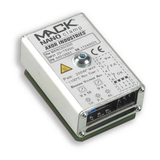
Page 18: Product Plate And Ordering Code
DC Brushed 1 = with (opt)(for case B only) FEEDBACK: CONTROL MODE: X = Standard CB = CanBus (std) R = Resolver (for case B only) MB = RS 485 MODBUS-RTU (opt) AXOR Industries Nano Mack ® ver.1 rev.11/'19 Service Manual... - Page 19 AXOR sas - Viale Stazione 5, Montebello Vic.no (VI) Italia - Tel. +39 0444440441 - Fax +39 0444440418 - info@axorindustries.com FIG.2 (Test Certifi cate) Note: It is recommended that the client retains the test certifi cate of both drive and motor. AXOR Industries Nano Mack ®...
- Page 21 Chapter 2 Installation 2.1 General Advices ....................22 2.2 Environmental conditions ..................24 2.3 Cables characteristics ..................25 2.4 Note about cable shielding ................... 27 2.5 Basic installation ....................28 2.6 Backup Supply connections .................. 31 2.7 Power & Backup common source ................32 2.8 Power supply connections..................
-
Page 22: General Advices
• Monthly clean drives from external dirt and dust deposits. • ADOPT ALL NECESSARY MEASURE TO AVOID DUST DEPOSITS INSIDE THE DRIVE. Disposal The disposal should be carried out by a certified company. AXOR Industries Nano Mack ® ver.1 rev.11/'19... - Page 23 (for a time determined by the type of system). • During installation, avoid letting any residue with metallic components fall inside the drive. • Protect the drive from excessive mechanical vibrations in the electrical box. AXOR Industries Nano Mack ® ver.1 rev.11/'19...
-
Page 24: Environmental Conditions
• Monthly check the internal cleaning of the electrical panel and define an accurate cleaning plane, according to using norms (for example CEI EN 60439-1). • Monthly check drive case for excess dust or dirt, that could interfere with the correct dissipation of the drive. AXOR Industries Nano Mack ® ver.1 rev.11/'19... -
Page 25: Cables Characteristics
The cable length must be shielded and 3m Max. Notes: • Avoid crossing, overlapping and twisting cables together. If it is absolutely necessary to cross them, do so at 90°. • Use only copper conductors for cabling. AXOR Industries Nano Mack ® ver.1 rev.11/'19 Service Manual... - Page 26 SPHD-001T-P05 26...22 AWG 1,5 mm ~ 1,5...2 mm housing connector: 0,13...0,33 mm PHDR-18VS Crimp contact: SPHD-001T-P05 26...22 AWG 1,5 mm ~ 1,5...2 mm housing connector: 0,13...0,33 mm PHDR-08VS Crimp tool: WC-240 AXOR Industries Nano Mack ® ver.1 rev.11/'19 Service Manual...
-
Page 27: Note About Cable Shielding
The shield of the motor cable (power and signal cables) are connected as follows: • Drive side (0,2m) remove the outside sheath and fix shield to the zinced panel, by using a U-clamp: POWER CABLE DRIVE MOTOR Max 0,2m Max 10m AXOR Industries Nano Mack ® ver.1 rev.11/'19 Service Manual... -
Page 28: Basic Installation
1 3 5 7 3 4 5 6 2 4 6 8 ALL ENCODER’S CABLE INTERNAL SHIELDS (NO EXTENAL SHIELD) FUSE (F ) POWER SUPPLY WITH TRANSFORMER (DON’T USE AUTOTRANSFORMER) ZINCED PANEL AXOR Industries Nano Mack ® ver.1 rev.11/'19 Service Manual... - Page 29 LENGHT MAX 10 cm MKN60/25-B-X-CB-Sxxx X000/X000 00000000 00000000 FUSE (F ) TWISTED LENGHT MAX 15 cm POWER SUPPLY BACKUP SUPPLY WITH TRANSFORMER (DON’T USE AUTOTRANSFORMER) ZINCED PANEL AXOR Industries Nano Mack ® ver.1 rev.11/'19 Service Manual...
- Page 30 13- Configure the drive setting for the relative operative mode (see cap. 4.1 Operative Modes on page 64). 14- Save in Eeprom and power off and on the drive to apply all the settings. 15- Execute the tests on the drive and the motor. AXOR Industries Nano Mack ® ver.1 rev.11/'19...
-
Page 31: Backup Supply Connections
÷ • Accepted voltage: 12 24VDC; • Max current required for the external supply: 0.1A; • We suggest to insert the F (see cap. 1.3 Technical Data on page 11) fuse; AXOR Industries Nano Mack ® ver.1 rev.11/'19 Service Manual... -
Page 32: Power & Backup Common Source
Capacitor ≥ In / 2 RMS( 10 khz ) RS ( OHM ) ≥ 20 000 000 / C ( uF ) D ( I ≥ Ipeak ( A ) * 2 AXOR Industries Nano Mack ® ver.1 rev.11/'19 Service Manual... -
Page 33: Power Supply Connections
C (uF) ≥ In ( A ) * 20 Capacitor ≥ In / 2 RMS( 10 khz ) RS ( OHM ) ≥ 20 000 000 / C ( uF ) AXOR Industries Nano Mack ® ver.1 rev.11/'19 Service Manual... - Page 34 Ri = Armature motor resistance with brushes. In = Rated current at nominal torque. The factory suggests keeping a margin by choosing AC voltage to avoid too high voltage during the deceleration phases of the motor. AXOR Industries Nano Mack ® ver.1 rev.11/'19...
- Page 35 This resistance discharges the capacitor when amplifier is disconnected after power supply switch off. The value can be calculated with the following formula : RS (Ohm) = 20 000 000 C(uF) P(W) = V2 AXOR Industries Nano Mack ® ver.1 rev.11/'19 Service Manual...
-
Page 36: Regen Resistance Connections
• Insert the fuse F (see cap. 1.3 Technical Data on page 11). • Do not mount the resistor on surfaces which can be damaged by heat. • If the resistors are mounted externally, protect them. AXOR Industries Nano Mack ® ver.1 rev.11/'19... - Page 37 Notes: • To deactivate the BRAKING function setup the "Resistance value", "Absorbed energy" and "Power" to 0. • Save to Eeprom and power off and on the drive in order to apply the setting. AXOR Industries Nano Mack ® ver.1 rev.11/'19...
-
Page 38: Motor Power Connection
Max 0,2m Max 10m motor's carcass. ATTENTION: Before enabling the drive be sure the type of motor setted in the drive is correct (see cap. 5.4 Motor / Feedback on page 96). AXOR Industries Nano Mack ® ver.1 rev.11/'19 Service Manual... - Page 39 Navigate to the Current Loop, insert the motor current ( I Rms ) and motor peak current( I Peak ). Run the tool PI Calculator. Insert the detail, calculate and apply. Save in Eeprom and reboot the drive. AXOR Industries Nano Mack ® ver.1 rev.11/'19...
-
Page 40: Motor Feedback Connections
A) CHA leads CHB for CW rotation as viewed from the motor’s front side; B) CHZ is on the falling edge of HALL U signal; HALL U MOTOR’S FRONT SIDE 120° HALL V HALL W CW ( CLOCK WISE ) AXOR Industries Nano Mack ® ver.1 rev.11/'19 Service Manual... - Page 41 SERIAL INCREMENTAL ENCODER FEEDBACK connection (See Note) Note: • The earth connection of the encoder cable’s shield must be made on the zinc-coated panel (using a U-clamp) near the drive (0,2 m). AXOR Industries Nano Mack ® ver.1 rev.11/'19 Service Manual...
- Page 42 U-clamp) near the drive (0,2 m). FEEDBACK Configuration In the software interface, under Motor/Feedback, it's possible to setup the correct feedback with the relative settings (see cap. 5.4 Motor / Feedback on page 96). AXOR Industries Nano Mack ® ver.1 rev.11/'19...
-
Page 43: Digital Inputs Connection
Under FUNCTIONS is possible to assign a function from the list (see cap. 5.8 Digital I/0 window on page 104) to the digital input, if required form the function the VALUE box will be enabled. AXOR Industries Nano Mack ®... -
Page 44: Digital Outputs Connections
• The led under HW indicates the hardware status. • An/D.OUT 1 switch between analog or digital based on the function selected (see cap. 5.8 Digital I/0 window on page 104 and see cap. 5.9 Analog I/O window on page 107 for detail). AXOR Industries Nano Mack ®... -
Page 45: Analog Inputs Connections
Direction" parameter in the "Velocity Loop" window (from Positive to Negative). ANALOG DIFFERENTIAL INPUTS ( An.IN 1+/- ) configuration ANALOG INPUTS window allow to setup some filters on the analog input (see cap. 5.9 Analog I/O window on page 107). AXOR Industries Nano Mack ® ver.1 rev.11/'19... - Page 46 • Voltage: ±10V Max ANALOG DIFFERENTIAL INPUTS ( An.IN Ref.Torque ) configuration ANALOG INPUTS window allow to setup some filters on the analog input (see cap. 5.9 Analog I/O window on page 107). AXOR Industries Nano Mack ® ver.1 rev.11/'19...
-
Page 47: Limit Switch Connections
PStop & NStop HARDWARE STATUS SOFTWARE STATUS ENABLED DISABLED LIMIT SWITCH connection with P+N Stop Nano Mack +24VDC (P+N Stop) DGT-IN2 AGND 0 VDC LIMIT SWITCH configuration with P+N Stop AXOR Industries Nano Mack ® ver.1 rev.11/'19 Service Manual... -
Page 48: Clock/Dir Inputs Connections
• Set the operative mode "5:Gearing" (see cap. 4.7 Gearing on page 72), "6:Pulse/Dir Mode" (see cap. 4.8 Pulse/Dir Mode on page 74) or "8:CW/CCW" (see cap. 4.12 CW/CCW on page 83), and the relative setting with the software Interface . AXOR Industries Nano Mack ®... -
Page 49: Rs485 Connections
In the software interface, under GENERAL/SETTINGS, set the ID and the RS485 baud rate. Always save in Eeprom to save the settings. Notes: Ensure that each drive is allocated with a unique ID and the same baud rate. • AXOR Industries Nano Mack ® ver.1 rev.11/'19 Service Manual... -
Page 50: Canbus Connections
• The bus-line must be terminated at both ends by RESISTORS (120 Ohm, 1/4W). • See "CanOpen/Ethercat Reference Manual" for a more detailed description about the Can- Open protocol implemented on the drive. AXOR Industries Nano Mack ® ver.1 rev.11/'19... - Page 51 CanBus baud rate. Save always in Eeprom to save the settings. Notes: nsure that each drive is allocated with a unique ID and the same baud rate. Otherwise, • E the network may hang. AXOR Industries Nano Mack ® ver.1 rev.11/'19 Service Manual...
-
Page 52: Led
(fixed) ● (blinking) ● ALARM (fixed) ● ● ⇔ ⇔ ONLY BACKUP VOLTAGE green (alternate) LED positions: MKN60/25-B-X-CB-Sx X000/X000 00000000 0000000 0 LED s ta tus +AT- AXOR Industries Nano Mack ® ver.1 rev.11/'19 Service Manual... - Page 55 Chapter 3 Diagnostic 3.1 Alarms....................... 56 3.2 Problem solving ....................58...
-
Page 56: Alarms
Possible short-circuit in the regen resistance circuit. 18 Reserved 19 Reserved V Backup The backup voltage is out of supported range. 21 Reserved Malfunction in the Safe Torque Off safety function or wrong sequence. AXOR Industries NanoMack ® ver.1 rev.11/'19 Service Manual... - Page 57 - AUTO = auto-reset when out of the problem condition; - NO = is not resettable with the reset input, need to be restarted removing and applying the backup supply; AXOR Industries NanoMack ® ver.1 rev.11/'19 Service Manual...
-
Page 58: Problem Solving
SOLUTION FOR ALARM 4 ( Hall ): ● Verify the cell's wire connection and feedback setting ( see cap. 2.11 Motor Feedback connections on page 40 ), reset the alarm, then enable the drive. AXOR Industries NanoMack ® ver.1 rev.11/'19... - Page 59 ● Verify if the connection are correct. ● Verify if there are any mechanical block. ● With the software interface check: • The Max Position Error parameter and the dynamic gains under Position Loop; AXOR Industries NanoMack ® ver.1 rev.11/'19...
- Page 60 ● Verify if there are any mechanical block. ● With the software interface check: • The Max Position Error parameter and the dynamic gains under Position Loop; • The dynamic gains under Velocity Loop; AXOR Industries NanoMack ® ver.1 rev.11/'19...
- Page 61 31 ), backup supply is required to startup the drive. DRIVE DOESN’T COMMUNICATE ● Verify the USB cable is correctly connected. ● Try to replace the USB cable. ● Be sure the driver is installed. AXOR Industries NanoMack ® ver.1 rev.11/'19 Service Manual...
- Page 63 Chapter 4 Operative Modes 4.1 Operative Modes ....................64 4.2 Analog Speed ..................... 65 4.3 Digital Speed ...................... 67 4.4 Analog Torque ....................68 4.5 Digital Torque ..................... 70 4.6 Position Mode ..................... 71 4.7 Gearing ......................72 4.8 Pulse/Dir Mode ....................74 4.9 Homing - Settings ....................
-
Page 64: Operative Modes 4.1 Operative Modes
This is useful for adjustments of the speed loop. ANALOG to The motor moves between two programmable positions corresponding POSITION the Min. and Max. voltages at the dedicated pins. DIGITAL POSITION The motor moves between two digital positions. AXOR Industries NanoMack ® ver.1 rev.11/'19 Service Manual... -
Page 65: Analog Speed
An. IN 1 + ANAL_REF An. IN 1 - CN-GND 3- Execute the settings of the offset of the velocity analog input reference via SpeederOne.2 interface: • Open the "Analog Inputs" window run AutoOffset. AXOR Industries NanoMack ® ver.1 rev.11/'19 Service Manual... - Page 66 Note: • To change the sense of rotation apply the positive voltage reference to An.IN 1-, or change the Rotary Direction parameter in the Speed window (from Positive to Negative). AXOR Industries NanoMack ® ver.1 rev.11/'19...
-
Page 67: Digital Speed
Example: Suppose we want to set a digital torque reference equal to 5A, having a drive size of 10/20 (10A=rated current, 20A=peak current) insert in the window Torque Sat. the value 25, in fact (5x100)/20=25. The value 0,0% disable the function. AXOR Industries NanoMack ® ver.1 rev.11/'19... -
Page 68: Analog Torque
4- Enable analog torque control via software interface: a- Set the operative mode 2:Analog Torque; b- It is possible to limit the max torque by setting the % of Imax by the value Torque Sat.(the value 0,0% disable this function)(*). AXOR Industries NanoMack ® ver.1 rev.11/'19... - Page 69 (5x100)/20=25. The value 0,0% disable the function. ATTENTION: If the rotation is irregular or noisy, it should be necessary to adjust the gains of the velocity loop by using an adequate procedure. AXOR Industries NanoMack ® ver.1 rev.11/'19 Service Manual...
-
Page 70: Digital Torque
Example: Suppose we want to set a digital torque reference equal to 5A, having a drive size of 10/20 (10A=rated current, 20A=peak current) insert in the window Torque Sat. the value 25, in fact (5x100)/20=25. The value 0,0% disable the function. AXOR Industries NanoMack ® ver.1 rev.11/'19... -
Page 71: Position Mode
An.IN Ref. Torque An.IN 1 + Notes: • Connect An.IN 1 - to the GND; See "Positioner Manual Mack" for a more detailed description about the positioner implemented on the drives (contact Axor). AXOR Industries NanoMack ® ver.1 rev.11/'19 Service Manual... -
Page 72: Gearing
Example: Suppose we want to set a digital torque reference equal to 5A, having a drive size of 10/20 (10A=rated current, 20A=peak current) insert in the window Torque Sat. the value 25, in fact (5x100)/20=25. The value 0,0% disable the function. AXOR Industries NanoMack ® ver.1 rev.11/'19... - Page 73 Phase B advanced by Phase B delayed by 90 deg from phase A 90 deg from phase A Minimum required time width [μs] CK/DIR Signal Max. allowable input frequency Line Driver 500kHz Open Collector 200kHz AXOR Industries NanoMack ® ver.1 rev.11/'19 Service Manual...
-
Page 74: Pulse/Dir Mode
Example: Suppose we want to set a digital torque reference equal to 5A, having a drive size of 10/20 (10A=rated current, 20A=peak current) insert in the window Torque Sat. the value 25, in fact (5x100)/20=25. The value 0,0% disable the function. AXOR Industries NanoMack ® ver.1 rev.11/'19... - Page 75 Clockwise rotation Counter-clockwise rotation ATTENTION: If the rotation is irregular or noisy, it should be necessary to adjust the gains of the speed loop or position loop by using an adequate procedure. AXOR Industries NanoMack ® ver.1 rev.11/'19 Service Manual...
- Page 76 4.8 Pulse/Dir Command Inputs time requirements: Signal Positive command Negative command Minimum required time width [μs] CK/DIR Signal Max. allowable input frequency Line Driver 500kHz Open Collector 200kHz AXOR Industries NanoMack ® ver.1 rev.11/'19 Service Manual...
-
Page 77: Homing - Settings
Not used during homing. Denominator Not used during homing. Position Polarity Positive or Negative. This parameter enables a complete inversion of axis control. Feed Forward This improves the system’s dynamics. Suggested value: 100%. AXOR Industries NanoMack ® ver.1 rev.11/'19 Service Manual... - Page 78 0 rpm to the maximum speed (in this case 3000rpm). The real acceleration time from 0 rpm to 1000 rpm is 167ms, in fact: T_acc_homing [ms] = 100 rpm * 500 ms =167 ms 3000 rpm AXOR Industries NanoMack ® ver.1 rev.11/'19 Service Manual...
- Page 79 - a digital programmable input with function "Homing Sensor"; - an output with function "Homing OK". Homing sensor connection: Connect homing sensor to the digital input pin set with the "Homing Sensor" function. AXOR Industries NanoMack ® ver.1 rev.11/'19 Service Manual...
-
Page 80: Homing - Example
DGT-IN2 (Start Homing) digital input is kept high, independently of the DGT-IN1 digital in- put (see (B) in the figure). Example: homing procedure DGT-N1 (ENABLE) DGT-IN2 (START HOMING) DGT-IN3 (HOMING SENSOR) SPEED DGT-OUT1 (HOMING OK) AXOR Industries NanoMack ® ver.1 rev.11/'19 Service Manual... - Page 81 IN2 (Start Homing) input and then enabling the DGT-IN1 and DGT-IN2 digital inputs ((a) in figure). Esempio di procedura di homing: DGT-IN1 (ENABLE) DGT-IN2 (START HOMING) DGT-IN3 (HOMING SENSOR) SPEED DGT-OUT1 (HOMING OK) AXOR Industries NanoMack ® ver.1 rev.11/'19 Service Manual...
-
Page 82: Canbus - Settings
5- Connect a RESISTOR (120 ohm, 1/4W) between pins CAN H and CAN L of the last drive of the network. See "CanOpen/Ethercat Reference Manual" for a more detailed description about the CanOpen protocol implemented on the drives (contact Axor). AXOR Industries NanoMack ®... -
Page 83: Cw/Ccw
Example: Suppose we want to set a digital torque reference equal to 5A, having a drive size of 10/20 (10A=rated current, 20A=peak current) insert in the window Torque Sat. the value 25, in fact (5x100)/20=25. The value 0,0% disable the function. AXOR Industries NanoMack ® ver.1 rev.11/'19... - Page 84 Clockwise rotation Counter-clockwise rotation ATTENTION: If the rotation is irregular or noisy, it should be necessary to adjust the gains of the speed loop or position loop by using an adequate procedure. AXOR Industries NanoMack ® ver.1 rev.11/'19 Service Manual...
- Page 85 4.12 CW/CCW Inputs time requirements: Signal Positive command Negative command Minimum required time width [μs] CK/DIR Signal Max. allowable input frequency Line Driver 500kHz Open Collector 200kHz AXOR Industries NanoMack ® ver.1 rev.11/'19 Service Manual...
-
Page 86: Square Wave Period
Example: Suppose we want to set a digital torque reference equal to 5A, having a drive size of 10/20 (10A=rated current, 20A=peak current) insert in the window Torque Sat. the value 25, in fact (5x100)/20=25. The value 0,0% disable the function. AXOR Industries NanoMack ® ver.1 rev.11/'19... -
Page 87: Analog To Position Control
An. IN 1 - CN-GND Note: To change the sense of rotation apply the positive voltage reference to An.IN 1-, or change the Position Direction parameter in the Velocity Loop window (from Positive to Negative). AXOR Industries NanoMack ® ver.1 rev.11/'19 Service Manual... - Page 88 Eeprom.; e- enable/disable the drive by using the Enable/Disable buttons. ATTENTION: If the rotation is irregular or noisy, it should be necessary to adjust the gains of the Velocity loop or position loop. AXOR Industries NanoMack ® ver.1 rev.11/'19...
-
Page 89: Digital Position
Example: Suppose we want to set a digital torque reference equal to 5A, having a drive size of 10/20 (10A=rated current, 20A=peak current) insert in the window Torque Sat. the value 25, in fact (5x100)/20=25. The value 0,0% disable the function. AXOR Industries NanoMack ® ver.1 rev.11/'19... - Page 91 Chapter 5 SpeederOne.2 Interface 5.1 Interface ......................92 5.2 System Overview ....................94 5.3 General Settings ....................95 5.4 Motor / Feedback ....................96 5.5 Current Loop ....................100 5.6 Velocity Loop ....................101 5.7 Position Loop ....................103 5.8 Digital I/0 window ..................... 104 5.9 Analog I/O window ....................
-
Page 92: Interface
After the program is started with the drive powered and connected to the pc, the following window will appear: View Connection Drive Options Settings General File Info Options Drive Setting Pages AXOR Industries NanoMack ® ver.1 rev.11/'19 Service Manual... - Page 93 ModBus / Serial USB for the type of Manual Mode. Utility By clicking on “Utility” it is possible to found some useful tools. About This option shows the program version and additional information. AXOR Industries NanoMack ® ver.1 rev.11/'19 Service Manual...
-
Page 94: System Overview
• Motor Type: Current motor type selected • Feedback Type: Current Feedback type selected • Operative Mode: Current operative mode • ID(CAN/ETH/485): CanBus / EtherCat / ModBus ID • Can Baud Rate: CanBus Baud rate AXOR Industries NanoMack ® ver.1 rev.11/'19 Service Manual... -
Page 95: General Settings
• Digital Speed: Digital speed reference • Torque Sat.: Torque limit in % (0% means torque limit disabled) • Time Delay: Square wave reverse time • Position 1 : Position 1. • Position 2 : Position 2. AXOR Industries NanoMack ® ver.1 rev.11/'19 Service Manual... -
Page 96: Motor / Feedback
• Revolution (pulses/rev): It contain the value of encoder pulses/rev. • Phase Angle: It contain the phasing angle of the motor. Step, V. mot, RPM Mot change their function according to the configuration motor/encoder. AXOR Industries NanoMack ® ver.1 rev.11/'19... - Page 97 Resolution = hall cell number * 2 • Phase Angle: It visualizes the phasing angle of the motor, previously calculated with the “Au- toPhasing” procedures. All other parameters are not to be set. AXOR Industries NanoMack ® ver.1 rev.11/'19 Service Manual...
- Page 98 Setting these param- eters, it is possible to correct the slope of this characteristic. The speed limit is the Speed Limit parameter. AXOR Industries NanoMack ® ver.1 rev.11/'19...
- Page 99 • Resolution: insert the definition of one motor revolution (MICROSTEPS). All other parameters are not to be set. Note: At the first power-up happen the electrical phasing between motor and encoder, this can result in a slight movement of the motor. AXOR Industries NanoMack ® ver.1 rev.11/'19...
-
Page 100: Current Loop
The numerical range of this parameter varies from 0 up to 999. Ti: It is the integral time in “ms” of the current loop. The numerical range of this parameter varies from 0 up to 999ms. AXOR Industries NanoMack ®... -
Page 101: Velocity Loop
• Kp: It is the proportional gain of the speed loop. This setting optimizes the dynamic behavior of the motor. • Ki: It is the integral gain of the speed loop. This setting optimizes the dynamic behavior of the motor. AXOR Industries NanoMack ® ver.1 rev.11/'19... - Page 102 Kp to Kp2 ( the value 0 disable the function). • Pid Filter: It is a filter on the output of the speed regulator. • Feedback Filter: It is a filter on the feedback speed. AXOR Industries NanoMack ®...
-
Page 103: Position Loop
Number of pulses necessary to do the rotation setted in the numerator. • Position Polarity Positive or Negative. This parameter enables a complete inversion of axis control. • Feed Forward This improves the system’s dynamics. Suggested value: 100%. AXOR Industries NanoMack ® ver.1 rev.11/'19 Service Manual... -
Page 104: Digital I/0 Window
Near the name of each digital input/output there are two fields: - There is a menu that allows you to select a function; - There is a field where you can insert the auxiliary variable if necessary. AXOR Industries NanoMack ®... - Page 105 “Pstop” function is not active with a high signal on the dedicated input. • Remember to save to the EEPROM all settings made on the programmable digital input in order to make them permanent. AXOR Industries NanoMack ® ver.1 rev.11/'19...
- Page 106 Digital output that allows to control an electromechanical brake motor via an external relay. 28:ZeroToggle Every time the motor passes form the the zero encoder, the output is toggled. 31:Blink The output is switched about every 500ms. AXOR Industries NanoMack ® ver.1 rev.11/'19 Service Manual...
-
Page 107: Analog I/O Window
Voltage in “mV” on the analog inputs taken as zero reference. • Filter Filter in “ms” on the analog input signal. • Auto Offset This button automatically execute the settings of the offset. AXOR Industries NanoMack ® ver.1 rev.11/'19 Service Manual... - Page 108 23:AbsSpeed The absolute value of the actual motor speed respect the max speed in analog signal (0÷10V). 25:ProgRef Programmable output voltage (0÷10V). 26:Saturation Max Output voltage (10V). 27:Half Half Output voltage (5V). AXOR Industries NanoMack ® ver.1 rev.11/'19 Service Manual...
-
Page 109: Alarms Window
5.10 Alarms window This window show if there is any fault state of the drive. For detail about the alarms ( see cap. 3.1 Alarms on page 56 ). AXOR Industries NanoMack ® ver.1 rev.11/'19 Service Manual... -
Page 110: Homing Window
(which is found during homing process). It is measured in pulses and the allowed values are in ranges: +/-(2^32-1). This value is assigned to the home position found at the end of a successful homing process. AXOR Industries NanoMack ®... -
Page 111: Braking Resistor Window
The value of the resistance in Ohm. Absorbed energy The absorbable adiabatic energy of the resistor in joule. Power The resistance braking power in Watt. Braking Voltage Level of voltage when the drive start braking. AXOR Industries NanoMack ® ver.1 rev.11/'19 Service Manual... -
Page 112: Oscilloscope
5.13 Oscilloscope Clicking on "Oscilloscope" it is possible to open the digital oscilloscope. The oscilloscope functions as a normal two channel digital oscilloscope and it allows visualizing: motor speed, phase current, position error, etc. AXOR Industries NanoMack ® ver.1 rev.11/'19... - Page 113 START/STOP DATA ACQUISITION: It starts data acquisition in both modes It stops data acquisition in Continuous Single or Continuous Acquisition. Acquisition mode, or in Single Acquisition mode if there is not a trigger event. AXOR Industries NanoMack ® ver.1 rev.11/'19 Service Manual...
- Page 114 Delay is ignored. The default value set for the Delay parameter is in the middle window. AXOR Industries NanoMack ® ver.1 rev.11/'19...
- Page 115 The unit of vertical scale is automatically set by choosing an input signal: • Rpm/div for speed • mA/div or A/div for current • Pulses/div for position error However, it is possible to change the scale selecting from values in the Scale menu. AXOR Industries NanoMack ® ver.1 rev.11/'19 Service Manual...
- Page 116 Trigger click on Auto button. c) Time base set to 200ms/div. d) Channel 1: View select Speed[rpm]. Scale select 500rpm/div. e) Channel 2: View select U Phase Current[A]. Scale select 2A/div. AXOR Industries NanoMack ® ver.1 rev.11/'19 Service Manual...
- Page 117 • To visualize more periods of input signals increase Time Base parameter. • To visualize less periods of input signals decrease Time Base parameter. In the above visualized trace, it is not necessary to change the time base. AXOR Industries NanoMack ®...
- Page 118 2. Select Single Acquisition. 3. Click on icon . 4. At each new desired acquisition click on icon . Doing the adjustments described above, we acquired the traces illustrated in the following: AXOR Industries NanoMack ® ver.1 rev.11/'19 Service Manual...
-
Page 119: Profile Tool
= 20 + 60°/360° = 20 + 0,16 = 20,16 after this you must multiply by 65536 the obtained number like as follow: 20,16 * 65536 = 1321642,6 and insert in the Final Position parameter the integer part of the number found, in this case 1321642. AXOR Industries NanoMack ®... - Page 120 Setting correctly these parameters it is possible to be sure that these oscillation is contained in a range (Window Pos) for a time over the time set in "Window Time" parameter. AXOR Industries NanoMack ®...
- Page 121 For other drives it is not necessary to configure one by one the parameter of the single task but you can use the file saved before and load the parameter saved on the file. After this save the parameter into flash. AXOR Industries NanoMack ®...
-
Page 122: Diagnostic
5.15 Diagnostic This window allows you set all the parameters ( advance mode ): AXOR Industries NanoMack ® ver.1 rev.11/'19 Service Manual... -
Page 123: Save/Load
It allows you to save the drive configuration in a file on your PC. LOAD FILE It allows you to load the drive configuration from a file on your PC. BOOT MODE Put the drive in BOOT MODE. AXOR Industries NanoMack ® ver.1 rev.11/'19 Service Manual... -
Page 125: Conformity
In reference to noise immunity and noise emission the converters fulfil the requirement to the category second environment (industrial environment). If the installation of the drive is carried out differently than described in this manual, the user must carry out new measures to satisfy the requisites of law. AXOR Industries NanoMack ® ver.1 rev.11/'19...
Need help?
Do you have a question about the Mack Nano and is the answer not in the manual?
Questions and answers