Table of Contents
Advertisement
Advertisement
Table of Contents

Related Manuals for AXOR Industries MiniMagnum Series


Summary of Contents for AXOR Industries MiniMagnum Series
- Page 1 AXOR Industries MiniMagnum ver.1 rev.05/'15 Service Manual...
- Page 2 The dRive's iNsTallaTioN; foR moRe deTails see eNclosuRes oN The cd pRovided wiTh The dRive. usiNg The dRive iNcoRRecTly caN iNjuRe people oR maNage ThiNgs. fully RespecT The TechNical daTa aNd iNdicaTioNs oN coNNecTioN coNdiTioNs. AXOR Industries MiniMagnum ver.1 rev.05/'15 Service Manual...
-
Page 3: Table Of Contents
2.16 Emulated encoder outputs connection 2.17 Pulse/Dir inputs connections 2.18 Feedback signals connections 2.19 Multidrop connection 2.20 Canbus connection 2.21 RS485 connection 2.22 MiniMagnum power up 2.23 Motor Test 3) diagnostic 3.1 Display 3.2 Alarms index conformity AXOR Industries MiniMagnum ver.1 rev.05/'15 Service Manual... - Page 4 • Display and Keypad Manual • Alarms Manual • ModBus Manual • CanOpen Reference Manual • Cables Manual • Oscilloscope Manual • Procedures Manual (available only on request) • Safety Enable Function Manual (available only on request) AXOR Industries MiniMagnum ver.1 rev.05/'15 Service Manual...
- Page 5 1) description chapter 1 description 1.1 Description 1.2 General view MiniMagnum 1.3 Technical Data 1.4 Mechanical Dimension 1.5 Product plate and Ordering Code AXOR Industries MiniMagnum ver.1 rev.05/'15 Service Manual...
-
Page 6: Description
The velocity and position loop both work with sampling time of 250µs. • The current commutation is sinusoidal. feedBacK eNcodeR incremental encoder signals plus hall signals standard ResolveR 2, 4, 6, 8 pole optional AXOR Industries MiniMagnum ver.1 rev.05/'15 Service Manual... - Page 7 SPEEDER ONE between the drive and PC is done by a RS232 cable using sofTwaRe standard the ModBUS protocol. iNTeRface The software works on the following operating systems: Windows 98, Windows 2000, Windows XP. AXOR Industries MiniMagnum ver.1 rev.05/'15 Service Manual...
- Page 8 CBLS cable for motor feedback signal, encoder/resolver (meter multiple) CBLS power cable for motors series SuperSAX motors series SuperSAX All optional features have to be requested by using the proper ordering code (see "1.5 Product plate and Ordering code"). AXOR Industries MiniMagnum ver.1 rev.05/'15 Service Manual...
-
Page 9: General View Minimagnum
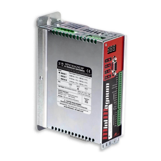
Analog and Digital RS232 comunication Chassis Inputs/Outputs, Relè OK (m2 connector) Emulated encoder outputs (j1 connector) (j2-j3 connectors, Feedback motor signals OPTIONAL) (encoder/resolver) CanBus, RS485 comunication (m4 connector) Auxiliary supply +24Vdc, Safety Enable Function AXOR Industries MiniMagnum ver.1 rev.05/'15 Service Manual... -
Page 10: Technical Data
250V (TL) (TL) (TL) (TL) (TL) (TL) (TL) (TL) (TL) ext. brak. 4A F 6A F 4A F 6A F 4A F 6A F resistor (f aux. pow. 6A (Time Lag) supply (f AXOR Industries MiniMagnum ver.1 rev.05/'15 Service Manual... -
Page 11: Mechanical Dimension
1.4 Mechanical Dimension Dimension in: [mm] Mechanical specifications drive assembly Panel mount external dimensions 201 x 141 x 66 weight 1,750 AXOR Industries MiniMagnum ver.1 rev.05/'15 Service Manual... -
Page 12: Product Plate And Ordering Code
RXdB: Black out dynamic Brake cBmd: canBus + multidrop interface 1= Present (opt) 1= Present (opt) 0= Not Present (std) 0= Not Present (std) R485: Rs485 interface 1= Present (opt) 0= Not Present (std) AXOR Industries MiniMagnum ver.1 rev.05/'15 Service Manual... - Page 13 2.15 Analog inputs connections 2.16 Emulated encoder outputs connection 2.17 Pulse/Dir inputs connections 2.18 Feedback signals connections 2.19 Multidrop connection 2.20 Canbus connection 2.21 RS485 connection 2.22 MiniMagnum power up 2.23 Motor Test AXOR Industries MiniMagnum ver.1 rev.05/'15 Service Manual...
-
Page 14: General Advices
• if the drive is dirty: the cleaning is reserved to the producer; • if the fans are dirty: clean them by using a dry brush. disposal The disposal should be carried out by a certified company. AXOR Industries MiniMagnum ver.1 rev.05/'15 Service Manual... - Page 15 The motor, as a result, is not controlled and can stop or go into neutral (for a time determined by the type of system). • During installation, avoid letting any residue with metallic components fall inside the drive. AXOR Industries MiniMagnum ver.1 rev.05/'15...
- Page 16 Please remember that "leakage currents" must be considered when settings differential devices in order to avoid useless interventions. For safety reasons connect the prepared terminal to earth before powering the drive. Incorrect con- nections make filter operation unreliable. AXOR Industries MiniMagnum ver.1 rev.05/'15 Service Manual...
-
Page 17: Positioning
Note: Arrange the power components (converters, main's filters, resistors, terminals, ... ) in bins of the electrical panel different from those reserved to the command or control systems (PLC, PC, CNC, regulators, ...). This improves the level of immunity to interference of the system. AXOR Industries MiniMagnum ver.1 rev.05/'15... -
Page 18: Environmental Conditions
• The electrical box must have suitably filtered air vents. Leave the necessary space both above and below the converters. • Periodically check drive case and fans for excess dust or dirt, that could interfere with the correct dissipation of the drive. AXOR Industries MiniMagnum ver.1 rev.05/'15 Service Manual... -
Page 19: Cables
• Avoid crossing, overlapping and twisting cables together. If it is absolutely necessary to cross them, do so at 90°. • On request Axor provides motor signal cables series encoder or resolver for motors series Super- SAX. AXOR Industries MiniMagnum ver.1 rev.05/'15 Service Manual... -
Page 20: Connection To Ground And Earth
It refers to the earth connection. It refers to the connection of the shield to the drive's carcass as illustrated on page It refers to the connection of the shield to the connector's metal ring. AXOR Industries MiniMagnum ver.1 rev.05/'15... -
Page 21: Note About Cable Shielding
• drive side (20:50cm) remove the outside sheath and fix shield to the zinced pannel, by using a u-clamp: • motor side The shield is internally connected to the metal ring of the motor connector, thus to earth through the motor's carcass. AXOR Industries MiniMagnum ver.1 rev.05/'15 Service Manual... -
Page 22: Base Installation Procedure
11- Open the Speeder One interface. 12- Execute the tests on the drive and the motor. In the following page there is an example of a basic connection. AXOR Industries MiniMagnum ver.1 rev.05/'15 Service Manual... -
Page 23: Example Of Base Connection
Cap 2.11 Cap 2.14 DGT-OUT2 RTN DGT-IN5 Safety Enable Function, DGT-IN6 OPTIONAL SEF IN DGT-IN7 Cap 2.13 DGT-IN8 Auxiliary N.C. DGT-IN9 voltage +24V DGT-IN RTN Cap 2.9 +24VDC CHASSIS GROUND BAR MAIN EARTH AXOR Industries MiniMagnum ver.1 rev.05/'15 Service Manual... -
Page 24: Supply Connections
Pn= nominal power of each motor (VA), which can be calculated in this way: pn = n x cn / 9,55 Pn=nominal motor power (W) n= motor speed (rpm) Cn= motor nominal torque (Nm) • for single phase power supply use l1 and l2. AXOR Industries MiniMagnum ver.1 rev.05/'15 Service Manual... -
Page 25: Motor Power Connection
The earth connection of the power cable’s shield must be made on the zinc-coated panel (using a u-clamp) near the drive (20-50cm). Motor side: the shield is connected to connector's metal ring, so it is connected to ground through motor's carcass. AXOR Industries MiniMagnum ver.1 rev.05/'15 Service Manual... -
Page 26: Regen Resistance Connections
Note: In accordance with the used resistance, internal or external, we recommend to correctly set the Regen Resistance parameter in the "General Setting" window in the Speeder One interface: internal (if the internal resistance is used), external (if an external resistance is used). AXOR Industries MiniMagnum ver.1 rev.05/'15... -
Page 27: Relè Ok Connection
RElE' Ok connection MiniMagnum It is normally open when the drive is not supplied; it is normally closed when the drive is supplied and it has not active alarms. - 500mA max AC/DC AXOR Industries MiniMagnum ver.1 rev.05/'15 Service Manual... -
Page 28: Digital Inputs Connection
If there is the m3 connector (OPTIONAL), it provides five additional digital inputs and one of them is programmable (M3-7). • Connect pin m1-12 (dgT-iN RTN) to the ground bar of the system. AXOR Industries MiniMagnum ver.1 rev.05/'15 Service Manual... -
Page 29: Analog And Digital Outputs Connections
AN-OUT2 ANALOG2 They can be set by the Speeder One 470n interface. CN-GND AGND Note: We suggest to connect the shield on both sides: drive side follow the indications illustrated on paragraph 2.6. AXOR Industries MiniMagnum ver.1 rev.05/'15 Service Manual... -
Page 30: Analog Inputs Connections
The technical characteristics of TPRC input are as follows: Voltage: ±10v Max. Input impedance: 20k ohm. Note: We suggest connecting the shield on both sides: drive side, follow the indications illustrated on paragraph 2.6. AXOR Industries MiniMagnum ver.1 rev.05/'15 Service Manual... -
Page 31: Emulated Encoder Outputs Connection
ReceiveR cN inputs MiniMagnum RS485 RS485 RS485 CN-GND PGND commoN mode cN inputs MiniMagnum CN-GND PGND Note: We suggest connecting the shield on both sides: drive side, follow the indications illustrated on paragraph 2.6. AXOR Industries MiniMagnum ver.1 rev.05/'15 Service Manual... -
Page 32: Pulse/Dir Inputs Connections
2.6. ElEctRical aXiS (GEaRiNG) connection OPTIONAL MiniMagnum MiniMagnum (Slave) (Master) 220 220 220 220 Note: We suggest connecting the shield on both sides: drive side, follow the indications illustrated on paragraph 2.6. AXOR Industries MiniMagnum ver.1 rev.05/'15 Service Manual... -
Page 33: Feedback Signals Connections
Note: The ground connection of the external shield must Max 25m 20:50cm be made on the zinc-coated panel (using a u-clamp) near the drive (20-50cm). Drive Motor Motor side: the shield is connected to connector's metal ring. AXOR Industries MiniMagnum ver.1 rev.05/'15 Service Manual... - Page 34 Note: The ground connection of the external shield must Max 25m 20:50cm be made on the zinc-coated panel (using a u-clamp) near the drive (20-50cm). Drive Motor side: the shield is connected to connector's metal Motor ring. AXOR Industries MiniMagnum ver.1 rev.05/'15 Service Manual...
-
Page 35: Multidrop Connection
• Axor drives use modBus communication protocol specified in the modicon instructions (see http://www.modicon.com/techpubs/). For more information see enclosure "modbus manual" and "canOpen Reference manual" on the CD provided with the drive. AXOR Industries MiniMagnum ver.1 rev.05/'15 Service Manual... -
Page 36: Canbus Connection
CAN L PGND PGND dc-dc Converter dc-dc Converter PGND Note: Connect a ResisToR (120 ohm, 1/4w) between pins 1 and 2 of the j2 (or j3) connector of the last minimagnum dc-dc Converter PGND AXOR Industries MiniMagnum ver.1 rev.05/'15 Service Manual... -
Page 37: Rs485 Connection
MiniMagnum 2 PGND PGND dc-dc Converter dc-dc Converter PGND Note: Connect a ResisToR (120 ohm, 1/4w) between pins 1 and 2 of the j2 (or j3) connector of the last minimagnum dc-dc Converter PGND AXOR Industries MiniMagnum ver.1 rev.05/'15 Service Manual... -
Page 38: Minimagnum Tm Power Up
DGT-IN1 input (D), in order to enable the INTERNAL ENABLE also. If the DGT- IN1 is not disabled then re-enabled, the +24V INTERNAL ENABLE remains disabled and AUXILIARY the user cannot execute any movement. SUPPLY MAIN SUPPLY AXOR Industries MiniMagnum ver.1 rev.05/'15 Service Manual... -
Page 39: Motor Test
Number of motor poles (Motor window) Feedback type(Motor window) Encoder impulse/rev or resolver n° of poles (Motor window) Irms current(Current window) Ipk current (Current window) Speed Limit (Speed window) AXOR Industries MiniMagnum ver.1 rev.05/'15 Service Manual... - Page 40 9) At this point it is possible to set other parameters in reference to the desired operative mode (see enclosures "Operative modes manual", "additional features manual", "Speeder One interface" available on the CD provided with the drive. AXOR Industries MiniMagnum ver.1 rev.05/'15...
- Page 41 3) diagnostic chapter 3 diagnostic 3.1 Display 3.2 Alarms AXOR Industries MiniMagnum ver.1 rev.05/'15 Service Manual...
-
Page 42: Display
- - - input ENABLE is disabled and there are no alarms. This appears when there is the 24 up +24VDC auxiliary supply, but not the main supply. alxx There is alarm xx. AXOR Industries MiniMagnum ver.1 rev.05/'15 Service Manual... -
Page 43: Alarms
Check the AC power supply input and the 80% of the I t energy recovery value has working cycles. This is a visual alarm, it an- al10 been reached. ticipates the intervention of the "Maximum recovery" alarm. AXOR Industries MiniMagnum ver.1 rev.05/'15 Service Manual... - Page 44 If the problem persists contact Axor. homing error Check the homing setup, then reset the alarm Position error too high during the homing using the "Start Homing" function. al26 procedure. The motor stops, but it is not disabled. AXOR Industries MiniMagnum ver.1 rev.05/'15 Service Manual...
- Page 45 The speed value set in the drive was exceeded. sequentlyit will generate "AL31" which will initiate the Immediate Stop Function. You can find more information in enclosure "alarm manual" available in the CD provided with the drive. AXOR Industries MiniMagnum ver.1 rev.05/'15 Service Manual...
-
Page 46: Index
7, 31 encoder connection 33 Environmental conditions 18 equipment 8 Example of base connection 23 Expansion cards 8 External Protections 10 General view 9 Holding brake 8 installation procedure 22 KeyPad 7 AXOR Industries MiniMagnum ver.1 rev.05/'15 Service Manual... - Page 47 Regen resistance 26 Rele' OK 27 resolver connection 34 Safety 8 black-out dynamic brake function 8 safety enable function 8 Security standard 14, 15 Shielding 21 Speeder One 7 Storage 14 Transport 14 AXOR Industries MiniMagnum ver.1 rev.05/'15 Service Manual...
-
Page 48: Conformity
In reference to noise immunity and noise emission the converters fulfil the requirement to the category second environment (industrial environment). If the installation of the drive is carried out differently than described in this manual, the user must carry out new measures to satisfy the requisites of law. AXOR Industries MiniMagnum ver.1 rev.05/'15 Service Manual... - Page 49 AXOR Industries MiniMagnum ver.1 rev.05/'15 Service Manual...
Need help?
Do you have a question about the MiniMagnum Series and is the answer not in the manual?
Questions and answers