Table of Contents
Advertisement
Quick Links
Advertisement
Table of Contents

Related Manuals for AXOR Industries MACK NANO


Summary of Contents for AXOR Industries MACK NANO
- Page 2 This maNual coNTaiNs a descRipTioN of NaNo mack aNd a guideliNes foR The dRive's iNsTallaTioN. usiNg The dRive iNcoRRecTly caN iNjuRe people oR maNage ThiNgs. fully RespecT The TechNical daTa aNd iNdicaTioNs oN coNNecTioN coNdiTioNs. AXOR Industries NanoMack ® ver.1 rev.02/'17 Service Manual...
-
Page 3: Table Of Contents
4.4 Digital Torque 4.5 Analog Torque 4.6 Gearing 4.7 Clock/Dir Command 4.8 Homing - Procedures 4.9 Homing - Settings 4.10 Homing - Example 4.11 CanBus - Settings 4.12 Analog to Position Control AXOR Industries NanoMack ® ver.1 rev.02/'17 Service Manual... - Page 4 Nano Mack Operative Modes Nano Mack Status 5.5 Speed window 5.6 Current window 5.7 Motor window 5.8 Analog I/O window 5.9 Digital I/0 window 5.10 Position window 5.11 Homing window 5.12 Oscilloscope conformity AXOR Industries NanoMack ® ver.1 rev.02/'17 Service Manual...
- Page 5 1) description chapter 1 description 1.1 Description 1.2 General view NanoMack 1.3 Technical Data 1.4 Product plate and Ordering Code AXOR Industries NanoMack ® ver.1 rev.02/'17 Service Manual...
-
Page 6: Description
The motor moves between two programmable positions aNalog To corrisponding the min and max voltages at the dedicated standard posiTioN pins. It allows to communicate and control the drive by using the Rs485 modBus-RTu optional RS485 interface. AXOR Industries NanoMack ® ver.1 rev.02/'17 Service Manual... - Page 7 The converter is protected from short circuitry, the Max/Min safeTy Voltage, over-temperature of the converter & motor, I t of standard drive, I t of motor, etc. AXOR Industries NanoMack ® ver.1 rev.02/'17 Service Manual...
-
Page 8: General View Nanomack
00000000 00000000 MOTOR E E D B A C K 1 3 5 7 3 4 5 6 2 4 6 8 21.5 READY ( flash ) ( flash ) ALARM AXOR Industries NanoMack ® ver.1 rev.02/'17 Service Manual... - Page 9 AXOR Industries NanoMack ® ver.1 rev.02/'17 Service Manual...
-
Page 10: Technical Data
±10V (±5%) - 12bit (+/- an.diff.Ref.) common mode analog input ±10V (±5%) - 12bit (an.Ref.Torque) Mechanical specifications drive assembly Panel mount external dimensions 74 x 43 x 23 Weight AXOR Industries NanoMack ® ver.1 rev.02/'17 Service Manual... -
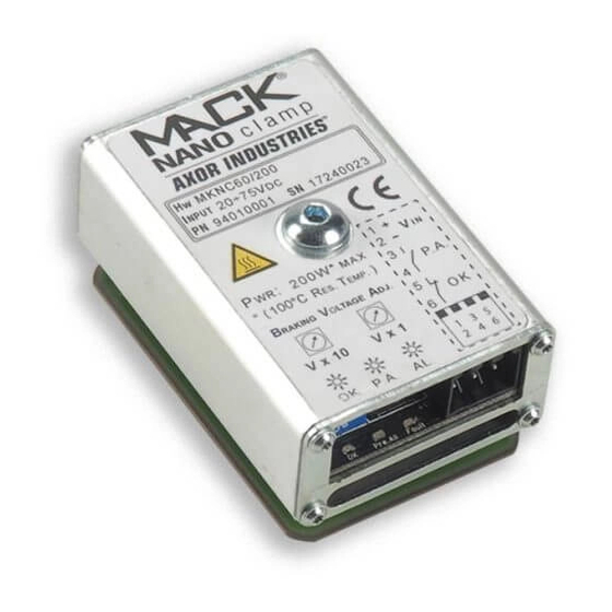
Page 11: Product Plate And Ordering Code
B = standard: Bl Brushless control mode: dc Brushed cB = CanBus (std) s = optional: mB = RS485 Mod Bus-RTU (opt) sm Stepper Bl Brushless dc Brushed feedback: X = standard AXOR Industries NanoMack ® ver.1 rev.02/'17 Service Manual... - Page 12 AXOR Industries NanoMack ® ver.1 rev.02/'17 Service Manual...
- Page 13 2.7 Motor power connection 2.8 Digital inputs connection 2.9 Digital outputs connections 2.10 Analog inputs connections 2.11 Clock/Dir inputs connections 2.12 Feedback signals connections 2.13 CanBus or RS485 connections 2.14 Nano Mack Led AXOR Industries NanoMack ® ver.1 rev.02/'17 Service Manual...
-
Page 14: General Advices
• monthly clean drives from external dirt and dust deposits. adopT all NecessaRy measuRe To avoid dusT deposiTs iNside The dRive. disposal The disposal should be carried out by a certified company. AXOR Industries NanoMack ® ver.1 rev.02/'17 Service Manual... - Page 15 The motor, as a result, is not controlled and can stop or go into neutral (for a time determined by the type of system). • During installation, avoid letting any residue with metallic components fall inside the drive. ® Nano mack • Protect the from excessive mechanical vibrations in the electrical box. AXOR Industries NanoMack ® ver.1 rev.02/'17 Service Manual...
-
Page 16: Environmental Conditions
(for example CEI EN 60439-1). • monthly check drive case for excess dust or dirt, that could interfere with the correct dissipation of the drive; in case of malfunctions contact axor. AXOR Industries NanoMack ® ver.1 rev.02/'17... -
Page 17: Cables
The cable length must be 3m max. interface Notes: • Avoid crossing, overlapping and twisting cables together. If it is absolutely necessary to cross them, do so at 90°. • Use only copper conductors for cabling. AXOR Industries NanoMack ® ver.1 rev.02/'17 Service Manual... - Page 18 SPHD-001T-P05 26...22 AWG 1,5 mm ~ 1,5...2 mm housing connector: 0,13...0,33 mm PHDR-18VS crimp contact: SPHD-001T-P05 26...22 AWG 1,5 mm ~ 1,5...2 mm housing connector: 0,13...0,33 mm PHDR-08VS Crimp tool: WC-240 AXOR Industries NanoMack ® ver.1 rev.02/'17 Service Manual...
-
Page 19: Note About Cable Shielding
The shield of the motor cable (power and signal cables) are connected as follows: • drive side (0,2 m) remove the outside sheath and fix shield to the zinced pannel, by using a u-clamp: Max 0,2m AXOR Industries NanoMack ® ver.1 rev.02/'17... -
Page 20: Base Installation Procedure
8- Connect the PC to the Nano Mack 9- Supply the drive with the backup supply and then the power supply. 10- Open the Speeder One interface. 11- Execute the tests on the drive and the motor. AXOR Industries NanoMack ® ver.1 rev.02/'17... -
Page 21: Supply Connections
The factory suggests keeping a margin by choosing AC voltage to avoid too high voltage during the deceleration phases of the motor; this value is 60 Vdc (44 Vac). Max value is 65Vdc and minimum value is 9Vdc. AXOR Industries NanoMack ®... - Page 22 This resistance discharges the capacitor when amplifier is disconnected after power supply switch off. The value can be calculated with the followig formula : Rs (ohm) = 20 x 1000000 c(uf) p(W) = v2 AXOR Industries NanoMack ® ver.1 rev.02/'17 Service Manual...
-
Page 23: Motor Power Connection
2.7 motor power connection MOTOR POWER (brushless motor) Nano Mack® Power (see Note) MOTOR POWER (DC motor) Nano Mack® Power (see Note) AXOR Industries NanoMack ® ver.1 rev.02/'17 Service Manual... - Page 24 Motor side: the shield is connected to connector's metal ring, so it is connected to ground through motor's carcass. aTTeNTioN: When using a dc motor, set the "dc motor" option in the "motor" window of speederone interface (see chapter 5). AXOR Industries NanoMack ® ver.1 rev.02/'17...
-
Page 25: Digital Inputs Connection
(without active alarms and if start up sequence is respected); if j1-3 is loW (0v), the motor is without torque. ® aTTeNTioN: The NaNo mack 's eNaBle/disaBle, By usiNg The eNaBle iNpuT, is NoT coNsideRed a secuRiTy fuNcTioN. AXOR Industries NanoMack ® ver.1 rev.02/'17 Service Manual... -
Page 26: Digital Outputs Connections
Example 3: Nano Mack® An/D.OUT 1 +24VDC 10nF Always use a relay with a diode in parallel. Vout (digital) = Vbackup Vout (analog) = 10V max Max. load for each output: 20[mA] AXOR Industries NanoMack ® ver.1 rev.02/'17 Service Manual... -
Page 27: Analog Inputs Connections
ANALOG COMMON MODE INPUT (An.Ref.Torque) used as torque analog reference Nano Mack® 4n7F +Vref An.Ref.Torque 15K4 TPRC_IN 3,3V REF_OP 4k02 The technical characteristics of An.Ref.Torque input are as follows: Voltage: ±10V Max. AXOR Industries NanoMack ® ver.1 rev.02/'17 Service Manual... -
Page 28: Clock/Dir Inputs Connections
2.11 clock/dir inputs connections CLOCK/DIR connection Nano Mack® Clock IN PULSE 100pF Dir IN 100pF AXOR Industries NanoMack ® ver.1 rev.02/'17 Service Manual... -
Page 29: Feedback Signals Connections
HALL U HALL V HALL W (vedi Note) Note: The earth connection of the encoder cable’s shield must be made on the zinc-coated panel (using a u-clamp) near the drive (0,2 m). AXOR Industries NanoMack ® ver.1 rev.02/'17 Service Manual... - Page 30 SERIAL AGND AGND Ch.A Ch.B Ch.Zs (vedi Note) Note: The earth connection of the encoder cable’s shield must be made on the zinc-coated panel (using a u-clamp) near the drive (0,2 m). AXOR Industries NanoMack ® ver.1 rev.02/'17 Service Manual...
- Page 31 HALL U HALL V HALL W (vedi Note) Note: The earth connection of the encoder cable’s shield must be made on the zinc-coated panel (using a u-clamp) near the drive (0,2 m). AXOR Industries NanoMack ® ver.1 rev.02/'17 Service Manual...
-
Page 32: Canbus Or Rs485 Connections
AXOR Industries NanoMack ® ver.1 rev.02/'17 Service Manual... -
Page 33: Nano Mack Led
In the Nano Mack there is a LED (red or green, fixed or blinking) that visualizes the system's status: coloR and sTaTe cause ● READY green (blinking) ● green (fixed) ● (blinking) ● ALARM (fixed) ● ● ⇔ ⇔ ONLY BACKUP VOLTAGE green (alternate) AXOR Industries NanoMack ® ver.1 rev.02/'17 Service Manual... - Page 34 3) diagnostic chapter 3 diagnostic 3.1 Alarms AXOR Industries NanoMack ® ver.1 rev.02/'17 Service Manual...
-
Page 35: Alarms
Error parameter, check the dy- al14 eter, because the "Max Position Error" namic gains, reset the alarm, then en- parameter is too small, or the dynamic able the drive. gains of the velocity-positioning loop are wrong. AXOR Industries NanoMack ® ver.1 rev.02/'17 Service Manual... - Page 36 Eeprom. supported. speedfollowing error Verify the phasing angle, if the prob- al32 The motor is rotating at a higher lem persists, contact Axor. speed then the required. AXOR Industries NanoMack ® ver.1 rev.02/'17 Service Manual...
- Page 37 AXOR Industries NanoMack ® ver.1 rev.02/'17 Service Manual...
- Page 38 4.4 Digital Torque 4.5 Analog Torque 4.6 Gearing 4.7 Clock/Dir Command 4.8 Homing - Procedures 4.9 Homing - Settings 4.10 Homing - Example 4.11 CanBus - Settings 4.12 Analog to Position Control AXOR Industries NanoMack ® ver.1 rev.02/'17 Service Manual...
-
Page 39: Operative Modes
This is useful for adjustments of the speed loop. eTheRcaT Available soon aNalog to The motor moves between two programmable positions corrisponding posiTioN the min and max voltages at the dedicated pins. AXOR Industries NanoMack ® ver.1 rev.02/'17 Service Manual... -
Page 40: Digital Speed
Example: Suppose we want to set a digital torque reference equal to 5A, having a drive size of 10/20 (10A=rated current, 20A=peak current) insert in the window Torque Sat. the value 25, in fact (5x100)/20=25. The value 0,0% disable the function. AXOR Industries NanoMack ® ver.1 rev.02/'17... -
Page 41: Analog Speed
10k0 CN-GND 47nF Note: To change the sense of rotation apply the positive voltage reference to -an.diff.Ref., or change the Rotary direction parameter in the speed window (from positive to Negative). AXOR Industries NanoMack ® ver.1 rev.02/'17 Service Manual... - Page 42 (contact axor). AXOR Industries NanoMack ®...
-
Page 43: Digital Torque
Example: Suppose we want to set a digital torque reference equal to 5A, having a drive size of 10/20 (10A=rated current, 20A=peak current) insert in the window Torque Sat. the value 25, in fact (5x100)/20=25. The value 0,0% disable the function. AXOR Industries NanoMack ® ver.1 rev.02/'17... -
Page 44: Analog Torque
4- enable the control via Speeder One interface: a- set operative mode "2:analogue Torque": b- save settings by clicking on icon save data to eeprom; c- enable/disable the drive by using the enable/disable buttons. AXOR Industries NanoMack ® ver.1 rev.02/'17... -
Page 45: Gearing
Phase B advanced by Phase B delayed by 90 deg from phase A 90 deg from phase A Minumun required time width [μs] ck/diR signal max. allowable input frequency line driver 500kHz open collector 200kHz AXOR Industries NanoMack ® ver.1 rev.02/'17 Service Manual... -
Page 46: Clock/Dir Command
Ratio Transmission ratio between revolutions (numerator) and pulses (denominator). Numerator Denominator Example: For 2500 pulses/revolution set as in figure(1/2500). 4- Save all settings by clicking on icon "save data to eeprom". AXOR Industries NanoMack ® ver.1 rev.02/'17 Service Manual... - Page 47 Counter-clockwise rotation aTTeNTioN: if the rotation is irregular or noisy, it should be necessary to adjust the gains of the speed loop or of the position loop by using an adeguate procedure (contact axor). AXOR Industries NanoMack ® ver.1 rev.02/'17...
- Page 48 4.7 clock/dir command inputs time requirements: Signal Positive command Negative command Minumun required time width [μs] ck/diR signal max. allowable input frequency line driver 500kHz open collector 200kHz AXOR Industries NanoMack ® ver.1 rev.02/'17 Service Manual...
-
Page 49: Homing - Procedures
"Zero speed" parameter. The home position will be set when the falling edge of home sensor is received. DGT-INx Homing Sensor Caso 1 Caso 2 AXOR Industries NanoMack ® ver.1 rev.02/'17 Service Manual... - Page 50 If the homing sensor output was already low at the homing start the motor axis simply turns counter-clockwise with a speed like the "Zero speed" parameter. The home position will be set when the rising edge of home sensor is received. DGT-INx Homing Sensor Case 1 Case 2 AXOR Industries NanoMack ® ver.1 rev.02/'17 Service Manual...
- Page 51 "Zero speed" parameter. The home position will be set on the first zero pulse after that the falling edge of the home sensor. DGT-INx Homing Sensor Zero Encoder Case 1 Case 2 AXOR Industries NanoMack ® ver.1 rev.02/'17 Service Manual...
- Page 52 Case 1 Case 2 i- homing immediate Enabling the digital input (active high) with this homing method the motor doesn’t move and the cur- rent position is set as the home position. AXOR Industries NanoMack ® ver.1 rev.02/'17 Service Manual...
-
Page 53: Homing - Settings
Example: If the maximum mechanical accepted error is 45° (1/8 mechanical turn), then the value to insert in the Max Position Error box is 8192, in fact 45°x65536/360°=8192. We suggest to insert the value 8192. AXOR Industries NanoMack ® ver.1 rev.02/'17... - Page 54 It allows limit the torqe %, during the homing procedure. speed This parameter sets the speed reference used during the homing process and it is given in “rpm”. The admitted values are in ranges between 10 and 1000 rpm. AXOR Industries NanoMack ® ver.1 rev.02/'17...
- Page 55 "Homing Offset" window. after the setting of the desired homing parameters save the changes using the “save To ee- pRom” function on the software interface, doing this the drive's setup will become permenent. AXOR Industries NanoMack ®...
- Page 56 - a digital programmable input with function homing sensor; - an outputput with function homing ok. For example: 5- homing sensor connection: Connect homing sensor to digital input pin set with "homing sensor" function. AXOR Industries NanoMack ® ver.1 rev.02/'17 Service Manual...
-
Page 57: Homing - Example
(start homing) digital input is kept high, independently of the d.iN1 digital input (see (B) in the figure). Esempio di procedura di homing: DGT-IN1 (ENABLE) DGT-IN3 (START HOMING) DGT-IN4 (HOMING SENSOR) SPEED DGT-OUT1 (HOMING OK) AXOR Industries NanoMack ® ver.1 rev.02/'17 Service Manual... - Page 58 (start homing) input and then enabling the d.iN1 and d.iN3 digital inputs ((a) in figure). Esempio di procedura di homing: DGT-IN1 (ENABLE) DGT-IN3 (START HOMING) DGT-IN4 (HOMING SENSOR) SPEED DGT-OUT1 (HOMING OK) AXOR Industries NanoMack ® ver.1 rev.02/'17 Service Manual...
-
Page 59: Canbus - Settings
7- Connect a RESISTOR (120 ohm, 1/4W) between pins CAN H and CAN L of the last drive of the network. See "canopen/ethercat Reference manual" for a more detailed description about the CanOpen protocol implemented on Axor's drives (contact Axor). AXOR Industries NanoMack ® ver.1 rev.02/'17... -
Page 60: Analog To Position Control
10k0 CN-GND 47nF Note: To change the sense of rotation apply the positive voltage reference to -an.diff.Ref., or change the Rotary direction parameter in the speed window (from positive to Negative). AXOR Industries NanoMack ® ver.1 rev.02/'17 Service Manual... - Page 61 (contact axor). AXOR Industries NanoMack ®...
-
Page 62: Speeder One Interface Nano Mack Main Menu Nano Mack Operative Modes Nano Mack Status
Nano Mack Operative Modes Nano Mack Status 5.5 Speed window 5.6 Current window 5.7 Motor window 5.8 Analog I/O window 5.9 Digital I/0 window 5.10 Position window 5.11 Homing window 5.12 Oscilloscope AXOR Industries NanoMack ® ver.1 rev.02/'17 Service Manual... -
Page 63: Speeder One Interface
If the operative mode (Windows 8 or Windows 10) does not allow the USB drivers update contact Axor. Attention: The parameter variation, via interface, should be done only by technical qualified personnel. AXOR Industries NanoMack ® ver.1 rev.02/'17 Service Manual... - Page 64 The program is started by clicking on "axormb.exe". The main window "axor servo drive" and the "select driver" window open simultaneously. ® Clicking ok (refer to MACK) on the "select driver" window you are connected to the Nano Mack AXOR Industries NanoMack ® ver.1 rev.02/'17 Service Manual...
- Page 65 By clicking on “file” it is possible to open, save or save as a config- uration file, or to compare two configurations or to exit the program. users Axor reserved information. AXOR Industries NanoMack ® ver.1 rev.02/'17 Service Manual...
- Page 66 It enables or disables the Open with I2t Drive function, which opening of the programmed ouTpuT during the alarm 6: "I t Drive". device id It allows setting the CanBus or Ethercat node ID. can Bus settings It allows setting the Baud rate of CanBus. AXOR Industries NanoMack ® ver.1 rev.02/'17 Service Manual...
- Page 67 When you select this option the program asks if it should execute motor phasing, if confirmed the motor automatically enables and executes. The phase angle is visualized in the “motor” window. about This option shows the program version and additional information, for example: ”Axor Servo Drive Software 2.0.4”. AXOR Industries NanoMack ® ver.1 rev.02/'17 Service Manual...
- Page 68 It loads all the values which are present on EEPROM to the drive. The program asks for confirmation. oscilloscope It opens the “oscilloscope” window. general settings It opens the “general setting” window. AXOR Industries NanoMack ® ver.1 rev.02/'17 Service Manual...
- Page 69 The motor is piloted with a “square wave” signal (for diagnostic use). 11: analog to position The motor moves between two programmable positions corrisponding the min and max voltages at the dedicated pins. 12÷20: op mode 12÷20 Operative modes for future use. AXOR Industries NanoMack ® ver.1 rev.02/'17 Service Manual...
- Page 70 By clicking on this button you can enable or disable the drive’s torque. ATTENTION: DRIVE'S ENABLE/DISABLE IS NOT CONSIDERED A SAFETY FUNCTION. AXOR Industries NanoMack ® ver.1 rev.02/'17 Service Manual...
-
Page 71: Speed Window
It is the integral gain of the speed loop. This setting optimises the dynamic behaviour of the motor. The range is between zero and 4000. If enabled, it is the proportional gain of the speed loop when the speed is 0 rpm. AXOR Industries NanoMack ®... -
Page 72: Current Window
It is the integral time in “ms” of the current loop. The numerical range of this parameter varies from 0 up to 999ms. Not to change this parameter before consulting axor bacause it is closely related to the motor. AXOR Industries NanoMack ®... -
Page 73: Motor Window
It visualizes the phasing angle of the motor, previously calculated with the “Tuning “motor phas- ing” procedures. step, v. mot, Rmp.mot change their function according to the configuration motor/encoder. AXOR Industries NanoMack ® ver.1 rev.02/'17 Service Manual... - Page 74 All other parameters are not to be set. Note: At the first powerup happen the electrical phasing beetwen motor and encoder, this can result in a slight movement of the motor. AXOR Industries NanoMack ® ver.1 rev.02/'17 Service Manual...
- Page 75 + encoder incremental With this coupling set only the following param- eter: • Resolution: insert the value of encoder puls- es/rev. All other parameters are not to be set. AXOR Industries NanoMack ® ver.1 rev.02/'17 Service Manual...
- Page 76 Setting these parameters, it is possible to correct the slope of this characteristic. The speed limit is the Speed Limit parameter. AXOR Industries NanoMack ® ver.1 rev.02/'17 Service Manual...
- Page 77 (MICROSTEPS). All other parameters are not to be set. Note: At the first powerup happen the electrical phasing beetwen motor and encoder, this can result in a slight movement of the motor. AXOR Industries NanoMack ® ver.1 rev.02/'17 Service Manual...
-
Page 78: Analog I/O Window
It visualises in “mV” the voltage measured on the analog inputs This value depends by the Offset, the Filter and the Dead Band settings. auto offset This button automatically execute the settings of the offset of the torque offset settings (“analog2”). AXOR Industries NanoMack ® ver.1 rev.02/'17... -
Page 79: Digital I/0 Window
Near the name of each digital input/output there are two fields: There is a menu that allows you to select a function; There is a field where you can insert the auxiliary variable if necessary. AXOR Industries NanoMack ®... - Page 80 “pstop” function is not active with a high signal on the dedicated input. • Remember to save to the eepRom all settings made on the programmable digital input in order to make them permanent. AXOR Industries NanoMack ® ver.1 rev.02/'17...
- Page 81 (not enabled) The actual position error can be monitored in main window of Speeder One interface by se- lecting Posit_Err option in Analog Out1 or Analog Out2 menu. AXOR Industries NanoMack ® ver.1 rev.02/'17...
-
Page 82: Position Window
Transmission ratio between revolutions(numerator) and pulses(denominator). Numerator Denominator It is suggested to use values around 1, especially in systems that requires high precision. You can find more information about Pulse/Direction mode on Chapter 4) Operative modes. AXOR Industries NanoMack ® ver.1 rev.02/'17 Service Manual... -
Page 83: Homing Window
It allows limit the torqe %, during the homing procedure speed This parameter sets the speed reference used during the homing process and it is given in “rpm”. The admitted values are in ranges between 10 and 1000 rpm. AXOR Industries NanoMack ® ver.1 rev.02/'17... - Page 84 “save To ee- pRom” function on the software interface, doing this the drive's setup will become permenent. You can find more information about homing on Chapter 4) Operative Modes. AXOR Industries NanoMack ®...
-
Page 85: Oscilloscope
Clicking on "oscilloscope" it is possible to open the digital oscilloscope implemented into the Axor Speeder One interface. The oscilloscope functions as a normal two channel digital oscilloscope and it allows visualizing: motor speed, phase current, position error, etc. Oscilloscope window AXOR Industries NanoMack ® ver.1 rev.02/'17 Service Manual... - Page 86 Single or Continuous Acquisition. visualized traces. it stops data acquisition in Continuous Acquisition mode, or in Single Acquisition mode if there is not a trigger event. AXOR Industries NanoMack ® ver.1 rev.02/'17 Service Manual...
- Page 87 Delay is ignored. The default value set for the Delay parameter is in the middle window. AXOR Industries NanoMack ® ver.1 rev.02/'17...
- Page 88 However, it is possible to change the scale selecting from values in the scale menu. For Channel 1 the scale will be visualized in red on the left, while for Channel 2 the scale will be visualized in blue on the right. AXOR Industries NanoMack ®...
- Page 89 Time base set to 200ms/div. d) Channel 1: View select Speed[rpm]. Scale select 500rpm/div. e) Channel 2: View select I_Phase U[A]. Scale select 2A/div. Impostazione parametri iniziali AXOR Industries NanoMack ® ver.1 rev.02/'17 Service Manual...
- Page 90 • To visualize more periods of input signals increase Time Base parameter. • To visualize less periods of input signals decrease Time Base parameter. In the above visualized trace, it is not necessary to change the time base. AXOR Industries NanoMack ®...
- Page 91 3. click on icon . 4. at each new desired acquisition click on icon . Doing the adjustments described above, we acquired the traces illustrated in the following: Traces visualized after parameter adjustment AXOR Industries NanoMack ® ver.1 rev.02/'17 Service Manual...
-
Page 92: Conformity
In reference to noise immunity and noise emission the converters fulfil the requirement to the category second environment (industrial environment). If the installation of the drive is carried out differently than described in this manual, the user must carry out new measures to satisfy the requisites of law. AXOR Industries NanoMack ® ver.1 rev.02/'17... - Page 93 AXOR Industries NanoMack ® ver.1 rev.02/'17 Service Manual...
Need help?
Do you have a question about the MACK NANO and is the answer not in the manual?
Questions and answers