
Related Manuals for Excelitas Technologies X-Cite NOVEM Series


Summary of Contents for Excelitas Technologies X-Cite NOVEM Series
- Page 1 X-Cite NOVEM User Guide ® Applies to X-Cite NOVEM Models: XT910 / XT910-F XT920 / XT920-F XT930 / XT930-F XT940 / XT940-F...
- Page 2 X-Cite® NOVEM User Guide 035-00710R rev.0 Made in Canada Excelitas Canada Inc. 2021 All rights reserved No part of this publication may be reproduced, transmitted, transcribed, stored in a retrieval system or translated into any language in any form by any means without the prior written consent of Excelitas Canada Inc.
-
Page 3: Table Of Contents
Table of Contents Safety ............................6 Glossary of Symbols ........................6 Safety Precautions ........................6 Getting Started ...........................8 System Components ........................8 System Layout ..........................10 Installation/Set-up ........................13 Operation – Manual Control ..................... 17 The Basics ............................ 17 SpeedDIAL Menu and Settings ....................19 3.2.1 SpeedDIAL Menu Structure .................... - Page 4 Low Illumination Intensity ......................33 Other Potential Symptoms & Questions ..................34 Routine Care and Maintenance ....................35 General ............................35 Cleaning - Exterior Surfaces ......................35 Cleaning - Optical Surfaces ......................35 Technical Specifications ......................37 General ............................37 Electrical ............................
- Page 5 X- Cite, formerly of Lumen Dynamics (which was acquired by Excelitas Technologies Corp. in November 2013) offers the Life Science and Analytical Instrumentation market a broad range of innovative lamp and LED fluorescence illumination and measurement solutions.
-
Page 6: Safety
1 Safety 1.1 Glossary of Symbols Symbol Meaning CAUTION - Risk of danger: consult accompanying documents WARNING – Eye damage may result from directly viewing ultraviolet light. Protective eye shielding and clothing must be used at all times. WARNING – UV light hazard. WARNING –... - Page 7 4. Always use this product with the external power supply and power cord set provided. Ensure the external power supply cord is connected to a grounded 3-pin outlet only. Any substitution of these components will invalidate regulatory certification of this product and may impair operating safety.
-
Page 8: Getting Started
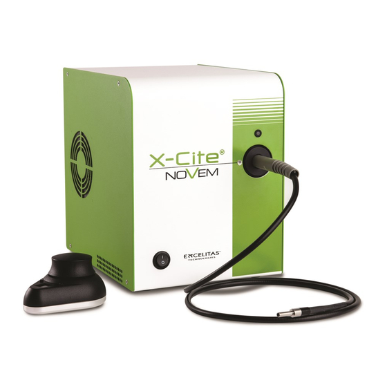
2 Getting Started 2.1 System Components This X-Cite system contains the following components: 1. X-Cite NOVEM unit (Series XT900), LEDs and dichroics are installed. 2. Clean-up Filters, installed (model numbers ending in “-F” only) 3. SpeedDIAL Manual Controller 4. Power Cord 5. -
Page 9: Figure 1 Front And Rear Panel Connections
Figure 1 Front and Rear Panel Connections Rotating Dial Display Screen (LCD) “up” / “down” buttons Figure 2 SpeedDIAL X-Cite® NOVEM User Guide 035-00710R rev 0... -
Page 10: System Layout
2.2 System Layout The LEDs installed in the unit, and their positions, depend on the configuration type. The X-Cite unit contains the following LED wavelengths: LED Position Fluorophore Wavelength XT910 XT920 XT930 XT940 Notes FURA-2 DAPI DAPI FITC Powered by LaserLED Hybrid Drive. - Page 11 Clean up Filters Installed in Configuration Option XT920-F Channel Fluorophore Wavelength Filter Installed DAPI 378/52 438/24 FITC 474/27 Blank Filter HD (500-600) 509/22 TRITC 554/23 mCherry 578/21 635/18 735/28 Clean up Filters Installed in Configuration Option XT930-F Channel Fluorophore Wavelength Filter Installed FURA-2 FURA-2/DAPI...
-
Page 12: Figure 3 Led And Filter Layout For All System Configuration Options
Figure 3 LED and Filter Layout for All System Configuration Options X-Cite® NOVEM User Guide 035-00710R rev 0... -
Page 13: Installation/Set-Up
2.3 Installation/Set-up For additional assistance with installation and set-up, videos are available. Refer to the X-Cite NOVEM website under “related content”. 1. Unpack a. Carefully unpack the unit and accessories from the shipping carton. b. When unpacking the light guide (liquid or quartz fiber), take care not to bend sharply or kink. -
Page 14: Figure 4 Single Filter And Rotary Filter Brackets
Figure 4 Single Filter and Rotary Filter Brackets 3. To install, remove or change clean-up filters in Rotary Filter Changer Important: Ensure that main unit is powered OFF before attempting to install filters a. Lay the X-Cite unit on its side, access panel side up. Remove the filter access panel with the 3mm hex tool. - Page 15 i. Place 25mm mounted filter in the bracket in the correct orientation advised by the filter manufacturer. Secure set screws (B). ii. Over a clean surface, turn filter bracket over to ensure the filter is firmly installed. iii. Reinstall the filter holder on the rotary assembly and secure the set screw (A). h.
-
Page 16: Figure 5 Correct Position For Fully Inserted X-Cite Llg And Llg With A And B Insertion Lines
Figure 5 Correct position for fully inserted X-Cite LLG and LLG with A and B insertion lines 6. Check Position of the Equipment a. The X-Cite unit should be positioned to avoid sharp bends and strain on the light guide. This applies to both liquid and quartz fiber light guides. -
Page 17: Operation - Manual Control
8. Connect USB (if using) a. Insert “B” (square) end into the “USB” port on rear of the unit. b. Insert “A” (flat) end into an available port on the computer. c. Note: For best performance, use the supplied USB cable (or one of equivalent quality and length), and plug directly into the computer. -
Page 18: Figure 6 Speeddial Display - Turning Led On/Off
Note: Using the “All” function on X-Cite NOVEM-FURA (models XT930 and XT930-F) is not recommended. The 340nm LED has a lower maximum temperature limit than the other LEDs. The heat generated while all LEDs are on may trigger an overheating error (Error 1) on the 340nm LED. Figure 6 speedDIAL Display –... -
Page 19: Speeddial Menu And Settings
3.2 SpeedDIAL Menu and Settings In addition to the intuitive intensity adjustment and illumination ON/OFF control, speedDIAL has several advanced settings and control options. To access the main menu, press and hold the dial for one (1) second. To navigate the menus, turn the dial to scroll through the options. -
Page 20: Lcd - Display Screen Brightness And Color Settings
3.2.2 LCD – Display Screen Brightness and Color Settings In the LCD sub menu, the time before the backlight is turned off (the backlight will turn back on with a movement of the speedDIAL), the backlight on the display screen can be turned on/off, set to a different brightness level, or set to a different color. -
Page 21: Srvc - Service Data
a. Select “Info” option from the main menu. b. Scroll through the LED list and click on the “LED#” of interest. c. To obtain the LED “in use” hours: i. Select the “Hour” menu option. ii. LED “hours of use” will be shown in one (1) hour increments from 0 to 999 hours. -
Page 22: Err
b. To obtain the unit serial number: i. Select the “SN” menu option. ii. Serial number of the unit will be shown. iii. Click dial to return to “Srvc” menu. c. To obtain the embedded software version numbers: i. Select the “S/W1” or “S/W2” menu items. The software version numbers will be shown in the format X.X.X. -
Page 23: Driver Update (Via Zip File)
b. Ensure X-Cite unit is connected to the computer with the USB cable. c. Ensure computer is connected to internet. d. Power on X-Cite unit. e. Driver installation will begin automatically. A dialogue box will confirm installation has started. A second dialogue box will confirm successful installation and provide a COM port number. -
Page 24: Verify Installation & Get Com Port Number
Navigate to the folder of extracted files from step c and select it. Wait for installation to complete. Windows will confirm when driver has been updated. k. Click Close. 4.1.3 Verify Installation & Get COM Port Number a. Open the “Device Manager” utility on the computer. b. -
Page 25: Software Developer's Kit (Sdk)
Figure 8 Device Manager, COM Port Listing 4.1.4 Software Developer’s Kit (SDK) The command list is available by request. To obtain the latest update, please contact Technical Support. Tips for specific use cases can be found in section 5.3. 4.1.5 Commercial Software Support a. -
Page 26: Grouping Controls / Compatibility Mode
4.1.6 Grouping Controls / Compatibility Mode To enable compatibility with existing device drivers for X-Cite XLED1 and X-Cite TURBO, it is possible to run X-Cite NOVEM in 4-channel or 6-channel mode by creating “Groups”. By assigning LEDs to a Group and turning on GROUP Mode, channel numbers are reassigned, allowing a sub-set of X-Cite NOVEM’s 9 channels to be controlled via USB or TTL. -
Page 27: Ttl & Analog
4.2 TTL & Analog 4.2.1 TTL Input Specifications a. Connector type: DB15 (female) b. Maximum low level : +0.8V c. Minimum high level : +2.2V d. Maximum high level: + 5.5V Typical input current: 800µA 4.2.2 TTL Signal and LED Status LED Status High 4.2.3 Analog Input Specifications... -
Page 28: Db15 Pin-Out And Cable Labels - Ttl Input
4.2.5 DB15 Pin-Out and Cable Labels – TTL Input Corresponding Wavelength Channel DB15 DB15 Cable Label XT910 XT920 XT930 XT940 Connector Pin XT910-F XT920-F XT930-F XT940-F Ground Ground Ground Ground Channel 9 735nm 735nm 340nm 785nm Channel 8 635nm 635nm 635nm 735nm Internal use... -
Page 29: Tips For Specific Use Cases
4.3 Tips for Specific Use Cases Refer to the SDK for full programming and command details. 4.3.1 Simultaneous Control to produce White Light Mode – USB To simultaneously control all LED channels with single commands: a. ON/OFF - Use the “turn all LEDs ON/OFF” command. b. -
Page 30: Response Times
4.4 Response Times 4.4.1 ON/OFF Response Time <100μs <1ms These typical response times apply to the individual LEDs and the LaserLED Hybrid Drive channels, assuming that the correct filter is already in place. If the rotary filter changer needs to engage, see section 4.4.2. -
Page 31: Troubleshooting
command is used to read the photodiode output. Refer to the X-Cite NOVEM command set (SDK) for more details about these commands. Note that the photodiode output is not calibrated. It is intended for relative comparisons only. For correlations to absolute power values, use a calibrated power meter at the end of the light guide or at the specimen plane. -
Page 32: Failure To Power Up
System (Sys) Errors Error Code Description Action Turn off the system and wait for the LED to cool down. Verify that the system has been installed with adequate clearance for ventilation, especially Sensor Input Error around vents on the side panel of the unit. If fan is not running or the problem persists contact technical support for assistance. -
Page 33: Low Illumination Intensity
Figure 10 Location and Removal of Fuse Tray in AC Receptacle b. If either or both of the fuses are open, replace with the same type (F6.3A, 250V). c. Note: To determine if a fuse is intact (i.e. OK) or open (i.e. blown), remove the fuse from the tray and check with a multi-meter set to resistance (Ω). -
Page 34: Other Potential Symptoms & Questions
b. Verify that everything in the microscope beam path is properly aligned and open, e.g. shutters, apertures, diaphragms, filters, filter cubes, etc. c. Verify that microscope filter sets are for the appropriate wavelengths. Verify that air objectives are clean / immersion objectives have enough of the appropriate fluid. -
Page 35: Routine Care And Maintenance
6 Routine Care and Maintenance 6.1 General This X-Cite unit is a very low maintenance system with only one consumable component – the liquid light guide. By maintaining the following conditions, performance will be maximized and risk of future problems will be reduced. 1. - Page 36 e. Let solvent evaporate and verify that the optical surface is clean. Repeat cleaning steps as necessary. Before reinstalling and/or using the optics, allow them to dry completely. CAUTION: Before using any solvent, consult the manufacturer’s Material Safety Data Sheet (MSDS) and your internal Health and Safety Advisor for proper handling, storage, and disposal instructions.
-
Page 37: Technical Specifications
7 Technical Specifications 7.1 General Main Unit speedDIAL Height 265mm (10.8″) 59mm (2.3″) Width 205mm (8.1″) 80mm (3.1″) Depth 270mm (10.6″) 112mm (4.4″) Weight 9kg (19.8lbs) 0.3kg (0.7lbs) Notes: a. Does not include clearance required for ventilation. b. Does not include clearance required for cables or light guide. 7.2 Electrical AC input information for external power supply: Power Supply... -
Page 38: Input/Output (I/O) Connections
7.5 Input/Output (I/O) Connections Connection Connection Style Purpose Remote - IN/OUT Mini DIN plug, 9pos Communication between speedDIAL and X-Cite unit to control LED and report status (on/off, intensity adjustment, system error, etc.) USB - IN/OUT Communication between computer and X-Cite unit to control LED and report status. -
Page 39: Regulatory Compliance
8 Regulatory Compliance 8.1 Product Safety and Electromagnetic Compatibility The X-Cite NOVEM has been tested and found to comply with product safety and electromagnetic compatibility requirements. For a complete list of tests and for certification details, please contact your X-Cite representative or visit https://www.excelitas.com/. 8.1.1 Laser Safety The X-Cite NOVEM is classified as Class 1 laser product according to IEC 60825-1: Safety of laser products –... -
Page 40: Ce Marking
8.2 CE Marking Council Directive 2014/35/EU Low Voltage Directive Council Directive 2014/30/EU EMC Directive Council Directive 2012/19/EU WEEE Directive Council Directive 2011/65/EU RoHS as amended by (EU) 2015/863 This is a class A product. In a domestic environment this product may cause radio interference in which case the user may be required to take adequate measures. -
Page 41: Weee Directive
8.4 WEEE Directive The symbol above indicates that this product should not be disposed of along with municipal waste, that the product should be collected separately, and that a separate collection system exists for all products that contain this symbol within member states of the European Union. ... -
Page 42: China Rohs
8.5 China RoHS The symbol above indicates that this product is in compliance with China RoHS requirements. Hazardous Substances Hexavalent Polybrominated Polybrominated Part Name Lead Mercury Cadmium Chromium biphenyls diphenyl ethers (Pb) (Hg) (Cd) (Cr (VI)) (PBB) (PBDE) Printed circuit board assemblies This table is compiled according to SJ/T 11364. -
Page 43: Korean Kc Certification
8.6 Korean KC Certification Warning statement EMC Registration is done on this equipment for business use only. If the product is used in the home, it may cause interference. This warning statement applies to products for business use. 8.7 Australia - RCM The symbol above indicates that this product is in compliance with the Electromagnetic Compatibility and Labelling requirements of the Australian Communications and Media Authority (ACMA). -
Page 44: Warranty & Repairs
9 Warranty & Repairs 9.1 Warranty Terms Excelitas warrants the original purchaser for a period of one (1) full year, calculated from the date of purchase, that the equipment sold is free from defects in material and workmanship. All repairs are warranted for 90 days. -
Page 45: Returning Equipment To Excelitas
9.2 Returning equipment to Excelitas 1. Please make a note of the problem encountered, the steps followed to isolate the problem and the result of any trouble shooting steps taken. 2. Contact the nearest Excelitas Service Center to obtain a Return Material Authorization (RMA) number. -
Page 46: Contact Information
10 Contact Information 10.1 General Excelitas Canada Inc. Tel: (905) 821-2600 Fax: (905) 821-2055 Toll Free: 1-800-668-8752 (USA and Canada) x-cite@excelitas.com http://www.excelitas.com/x-cite 10.2 Technical Support and Service For Technical Support and Service specific to Excelitas UV & Microscopy products: (905) 821-2600, option 3 1-800-668-8752, option 3 (USA and Canada) https://www.excelitas.com/ox_service_request_form 10.3 Accessories and Replacement Parts...
Need help?
Do you have a question about the X-Cite NOVEM Series and is the answer not in the manual?
Questions and answers