
Related Manuals for Shini SS-S1


Summary of Contents for Shini SS-S1
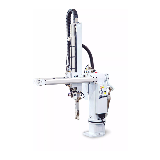
- Page 1 SS-S1 Standard Swing-arm Robot 1 User Manual Date: August, 2017 Version: V1.0 (English)
- Page 2 2(49)
-
Page 3: Table Of Contents
2.6.1.1 The Injection Molding Machine Output Signals ..........20 2.6.1.2 Robot Output Signals..................21 2.6.2 Euromap12 Interface .................... 22 2.6.2.1 Injection Molding Machine Output Signals ............23 2.6.2.2 Robot Output Signals..................24 GENERAL DESCRIPTION ..................... 25 3.1 SS-S1 S ....................25 ERIES BSTRACT 3.2 SS-S1 A ...................... 25 PPLICATION 3.3 SS-S1 F... - Page 4 3.4 F ........................26 UNCTIONS 3.4.1 Function Description..................... 26 3.4.2 Shock Absorber ....................26 3.4.3 Functions Adjustment ................... 27 3.4.3.1 Mold Change..................... 27 3.4.3.2 Reversing......................27 3.5 S ......................27 AFETY UNCTION 3.5.1 Safety Protection ....................27 3.5.2 Emergency Stop ....................28 3.6 A ....................
- Page 5 Table 2-1: SS-S Robot Specification List................15 Picture Index Picture 1-1: Lift Up Robot ....................... 11 Picture 2-1: Driling Sticker ...................... 14 Picture 2-2: SS-S1 Dimensions ....................14 Picture 2-3: Stop Package...................... 17 Picture 2-4: Y Stop Package ....................18 Picture 2-5: Rotate Cylinder ....................18 Picture 2-6: Magnetic Switch ....................
- Page 6 6(49)
-
Page 7: Safety
● Turn off power supply and compressed air before maintenance and adjustment. Also set up warming signs and safety fences. ● Please use parts of SHINI if there is any replacement is required. ● Our robots meet all corresponding safety standards. - Page 8 ● Unauthorized personnel must inform the relative supervisor and understand all safety rules before entering robot working area. ●Please order a new user manual from the manufacturer or vendor if the user manual is damaged. Product owner has the responsibility to ensure the operators, maintenance staffs and relative staffs have read user manual thoroughly.
-
Page 9: The Warning Marks And Its Meanings
1.3 The Warning Marks and Its Meanings Marks Meaning Do Not Touch Caution, danger Caution! Electric shock Caution! Mechanical injury Caution! High temperature No Flame 9(49) -
Page 10: Emergency Stop
Euromap12 and Euromap67 interface. Therefore when the emergency stop button on the molding machine is pressed the robot will also stop and vice versa. Any problem during using Shini robots, please contact our company or the local vendor. Headquarters & Taipei Factory: TEL:(02)26809119... -
Page 11: Storage
Any damage caused by transportation, please: 1) Feedback immediately to the transporting companies and our company. 2) Claim to the shipping company; fill in the file requests for compensation. 3) Retain damaged items for testing. During the wait for tests, do not return the damaged items. -
Page 12: Retirement
The following statements clarify the responsibilities and regulations born by any buyer or user who purchases products and accessories from Shini (including employees and agents). Shini is exempted from liability for any costs, fees, claims and losses caused by reasons below: 1. -
Page 13: Installation
2. Installation 2.1 Instruction 2.1.1 Safety Issue 1.Before installation, please read this chapter carefully. 2.Follow the installation guide to prevent accidents. 3.Please check robot and all parts in good condition. 4.Check anti-falling cylinder is normally. 5.Fix the robot base before operating. 6.Indicate the safety fence outside of the robot operation area. -
Page 14: Mounting Preparation
1. Avoid sharp pounding; collision and falling when transfer the robot to the top of IMM. 2. Adjust the torque spanner to 77Nm after the robot has been fixed on the right position; tighten the M10 × 30 hex socket bolt screws. 2.2 Dimensions (Unit: mm) Picture 2-2: SS-S1 Dimensions 14(49) -
Page 15: Model Specification
2.2.1 Model Specification Table 2-1: SS-S Robot Specification List Model SS-650-S1 SS-650T-S1 SS-750T-S1 IMM (ton) 50-200 50-200 150--250 Vertical Stroke (mm) 0--650 0—650 0--750 Crosswise Stroke (mm) 0--120 0—120 0--200 Swing Angle (deg) 50--90 50-90 50--90 Wrist Angle (deg) Max Load (kg) Min Pick-out Time (sec) Min Cycle Time (sec) Max Air Consumption... -
Page 16: Electrical Connection
2.3 Electrical Connection 2.3.1 Main Power Supply The power requirements are given on the serial plate of the robot. The power connection is provided through a normal power cord and a CEE plug. The power connection should be performed only by an authorized electrician according to applicable electric utility regulations. -
Page 17: Axes Adjustment
2.4 Axes Adjustment While adjusting, make sure that the robot cannot be run and that the compressed air supply is shut off. 2.4.1 Adjusting the X-Position Picture 2-3: Stop Package The x-position is determined by the stop package. The stopper is for adjusting the 0-position. Before running in to the mold range with the Y-axis for the first time, you must check whether the X-positions can be reached without damaging the mode and the Y-axis. -
Page 18: Adjusting The Z-Position
Picture 2-4: Y Stop Package If the Y-axis is shifted, also the withdrawal position changes. 2.4.3 Adjusting the Z-Position The Z-position is determined by adjusting the position of the shock absorber. Before adjusting, release the compressed air. 1) Loosen the nuts on the rotate cylinder 2) Adjust the rotate cylinder into the desired position 3) Tighten the nuts in place The Z-position must be adjusted so that the Y-axis can be fully run out. -
Page 19: Gripper And Suction Setting
During the robot operation, if the gripper not clamps the parts, the robot will stop operating and alarm. Picture 2-6: Magnetic Switch 2.6 Robot and IMM Interface SS-S1 series robots are available with 2 different interface versions to communicate with the injection molding machine: ●Euromap67 ●Euromap12 Both versions are described in the following chapters. -
Page 20: The Injection Molding Machine Output Signals
The robot-injection molding machine interface is designed according to the directives of Euromap67, which states: Unless otherwise noted, the signals, which are maintained during the described function. 2.6.1.1 The Injection Molding Machine Output Signals Contact No. Function Emergency stop channel 1 The emergency stop switch of the injection molding machine is used to interrupt the emergency stop circuit of the robot. -
Page 21: Robot Output Signals
The signal acknowledges “ejector back enabled” (see pin contact No.B3). Ejector forward position HIGH signal when the ejector is forward. The signal acknowledges “ejector forward enabled” (see pin contact No.B4). Core pullers 1 free for robot to approach HIGH signal when the core pullers are in position for removal of the injection moiling.(see pin contact No.B5) Core pullers 1 in position to remove molding HIGH signal when the core pullers are in position for removal of the injection molding.(see pin... -
Page 22: Euromap12 Interface
“.the signal must be maintained at least until the signal “ejector back “from the molding machine (see pin contact No.ZB3). Ejector forward enabled HIGH signal when the removal operation has been performed far enough for the motion “ejector back” to be carried out. the signal is HIGH for the duration of the motion “ejector back “.the signal must be maintained at least until the signal “ejector back “from the molding machine(see pin contact No.ZB4). -
Page 23: Injection Molding Machine Output Signals
2.6.2.1 Injection Molding Machine Output Signals Plug Contact No. Function Emergency stop of machine 1,9 The emergency stop switch of the injection molding machine is used to interrupt the emergence stop circuit of the robot. Mold open The switch contact (pin contact 16) is closed when mould opening position is equal or more than required position. -
Page 24: Robot Output Signals
2.6.2.2 Robot Output Signals Contact No. Function Enable mould close The switch contact (see pin contact No.32) is closed when the robot is retracted enough for start of mould closure. the switch contact must remain closed at least until “mould closed” (see pin contact No.12) Mould area free The switch contact is closed when the robot is retracted enough for start of mould closure. -
Page 25: General Description
3. General Description 3.1 SS-S1 Series Abstract The SS-S1 series robot is designed for rapid and precise removal of spure and runner from injection molding machine, and place them into granulator for recycling. Simple product removal is applicable with optional vacuum generator and EOAT. -
Page 26: Ss-S1 Features
3.3 SS-S1 Features 1. The guide rod used alloy material, small friction and wearable. 2. The gripper comes with sensor and rotate wrist device. 3. Shock absorber and proximity switch made rotate cylinder moves smoothly. 4. Shock absorber and magnetic switch made crosswise cylinder smoothly moves forward or backward. -
Page 27: Functions Adjustment
3.4.3 Functions Adjustment 3.4.3.1 Mold Change Fast mold changing design provides simple method for changing molds. The base is ℃ rotatable for 90 by releasing the handle Picture 3-2: Handle 3.4.3.2 Reversing The robot arm fixed on curved slide, easy to change robot reversing. The following are the steps: 1. -
Page 28: Emergency Stop
3.5.2 Emergency Stop There is the emergency stop button on the hand controller. When the emergency stop button is pressed, the robot will stop working. The gripper and vacuum valve and the vacuum generator are not disconnected in order to avoid dropping parts from the gripper. In addition, the hand controller will remain under power to allow indication of error messages. -
Page 29: Air Pressure Adjustment
Picture 3-5: Robot Base 3.6.4 Air Pressure Adjustment 1. After installing the robot, rotate the air pressure adjustment button which on the filter regulator, adjust the pressure to the 5bar (default setting). 2. All the drive-cylinder fittings are used speed control fitting. Adjust the air flow to change the speed of the drive-cylinder. -
Page 30: Adjusting The Swing-Out Angle
3.6.6 Adjusting the Swing-out Angle The range of swing-out angle is 50 to 90 degree. You can adjust the position of the shock absorber on the rotation cylinder to adjust the swing-out angle. a. When arm swing left; rotate the right buffer in counterclockwise to increase the swing-out angle, in clockwise direction is reversing. -
Page 31: Operation Instructions
4. Operation Instructions 4.1 Hand Controller 4.1.1 The Panel of Hand Controller Picture 4-1: The Panel of Hand Controller 4.1.2 Keys Arm up/down Arm forward/backward Gripper on/off Arm swing-in/swing-out Vacuum on/off Spare valve on/off (use to control the conveyor and transporter.) Mold close 4.2 Manually Operation Press... -
Page 32: Automatic Operation
1. The “mold open” signal. 2. Insure arms will not knock against surrounding subjects. ** Manual Input ** NoAct 4.3 Automatic Operation Press key, show the display, and enter into auto operating model. Auto time (AutoTime): Record current automatic cycle time. Set yield (SetYield): Anticipate the production quantity of the enactment. -
Page 33: The Function Setting
4.4.3 The Function Setting In stand-by page, press key to enter the function choice page. Press key on the hand controller, use cursor to choice the desired function, press key to change and save the setting. 1. Ejection relation (Eje.Use): NoUse: “Enable ejector forward”... - Page 34 1. Spare counter (PrerCnt): If the value is 00 for not using spare counter. If setting the value, the spare valve output counters according to movement of sub-interval mold. If value is 1 stands for each mold output the spare valve, 2 stands for two molds output spare valve once only.
-
Page 35: Molds Select
NoUse: not test the fully auto operating signals. Use: When having the fully auto operating signals, the robot can work in auto mode. When the signal cut off, the robot will stop when the action cycle finished. 4.4.5 Molds Select In stand-by page, press key to enter into molds choice page (No.0 to No.99 molds can be choiced). -
Page 36: Time Setting
step by step, after doing it, modification complete after press key and current recipe is saved. The robot will work and turn to next program. main arm down modes number steps number action action time : input one order without actions in the teach program. : delete one order from teach program. -
Page 37: I/O Monitor
4.4.9 I/O Monitor In stand-by or auto page, press key to enter into the I/O monitor page. Use the up/down key to move the cursor and monitor the input and output signals. INPUT OUTPUT LS SQL 1. UpLmt 1. DownValve 2. - Page 38 0212 rotate inside Program 3: Clip the moving side 0300 produce quantity 0301 open mold delay 0302 ejection delay 0303 main arm forward 0304 main arm down 0305 the main arm clip 0306 main arm backward 0307 main arm up 0308 main arm forward 0309 rotate outside 0310 main arm down...
-
Page 39: Error Correction
5. Error Correction Error Error Caused Error Correction 1. Emergency Stop key on the hand 1. Losing the Emergency Stop key on the After power on, the controller was pressed. hand controller. display on the hand 2. 37P plugs loosed or not connected. 2. - Page 40 4. Check I/O connecting wire. 5. Whether having trouble on power board. 1. Whether main clip valve testing function is reverse. Error Number 12 2. Whether the air pressure is too low. 04 Main Clip ON Main clip on, main clip limit no input. 3.
- Page 41 ON 07 MidMold Off 2. Whether having the signal of middle mode in the monitor. 3. Check I/O connecting wire. 4. Whether having trouble on power board. 1. When rotating in, check the indicator light of the rotary switch on or not. Error Number 51 Out limit and in limit no signal input at 2.
- Page 42 contact. 1. Losing the emergency stop key of the electronic control. Error Number 62 Injection molding machine carry out 2. Losing the emergency stop key of the 13 Emergency OFF emergency stop. injection molding machine. Emergency Event 3. Check the connection line of the emergency stop signal.
- Page 43 1. Down limit off or not. 2. Whether the magnetic valve having Error Number 78 Having the down limit signal, no trouble. MainDown OFF down action. Main down lmt ON 3. Check I/O connecting wire. 4. Whether having trouble on power board. 1.
-
Page 44: Maintenance
6. Maintenance 6.1 General Please observe the prescribed maintenance intervals. Proper maintenance ensures trouble-free functioning of the robot. Proper maintenance is necessary in order that the warrantee be fully enforceable. Maintenance should be performed by qualified personnel only. Maintenance and responsibility for safety equipment becomes the responsibility of the system operator once he accepts the robot. -
Page 45: Maintenance
6.3 Maintenance In accordance with the maintenance schedule, make robot operates in best way. Quarterly Maintenance Daily Maintenance Monthly Maintenance 1. Swab. 1. Use air gun to clean filter. 1. Brush grease to the 2. Filter drainage. 2. Check the screws on all parts whether guide shafts. -
Page 46: Electrical Control Charts
6.4 Electrical Control Charts 6.4.1 The Main Control Board Input Wiring Diagram Picture 6-1: The Main Control Board Input Wiring Diagram 46(49) -
Page 47: The Main Control Board Output Wiring Diagram
6.4.2 The Main Control Board Output Wiring Diagram Picture 6-2: The Main Control Board Output Wiring Diagram 47(49) -
Page 48: The Main Control Signal Wiring Diagram
6.4.3 The Main Control Signal Wiring Diagram Picture 6-3: The Main Control Signal Wiring Diagram 48(49) -
Page 49: The Main Control Panel Layout
6.4.4 The Main Control Panel Layout Picture 6-4: The Main Control Panel Layout 49(49)
Need help?
Do you have a question about the SS-S1 and is the answer not in the manual?
Questions and answers