Table of Contents
Advertisement
Quick Links
DXD/LTC
LTC option
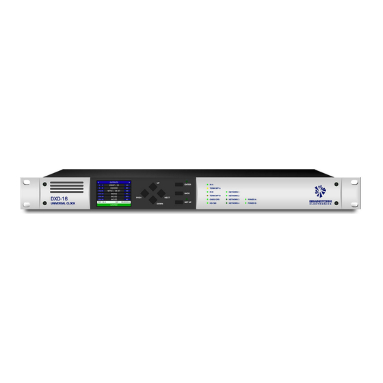
for the DXD-8 & DXD-16 Universal Clocks
Operations manual
Version 2.10
January 2021
All materials herein © Brainstorm Electronics, Inc.
Brainstorm Electronics reserves the right to change or modify the contents of this manual at any time.
Brainstorm Electronics, Inc.
www.brainstormtime.com
Advertisement
Table of Contents

Subscribe to Our Youtube Channel
Summary of Contents for Brainstorm Electronics DXD
- Page 1 DXD-8 & DXD-16 Universal Clocks Operations manual Version 2.10 January 2021 All materials herein © Brainstorm Electronics, Inc. Brainstorm Electronics reserves the right to change or modify the contents of this manual at any time. Brainstorm Electronics, Inc. www.brainstormtime.com...
- Page 2 7. Outputs Display - Main Rotation ....................8. Times Display - Status Mode ...................... 9. Appendix ..........................9.1 APPENDIX A: USING A 75Ω UNBALANCED OUTPUT ........9.2 APPENDIX B: BNC OUTPUT LEVEL ..............9.3 APPENDIX C: DB-25 CONNECTOR (DXD-16 ONLY) ........
- Page 3 This key is only valid for the model and serial number used when you placed the order. Enter this key in the FEATURE KEYS menu (10.5 on the DXD-8 and 11.5 on the DXD-16), under the main UTILITY menu. On the DXD-8, be sure to enter it in the TIME CODE line.
- Page 4 For time code, the Previous Daily Jam Event is the generator’s anchor point, until the Next Daily Jam Event. When the local time is too close to the set Daily Jam Time, a manual change will not occur until the next day. By forcing the DXD to recalculate both jam times manually, the operator has the option to make an immediate change.
- Page 5 Jan 1, 1970) per ST2059. The color field sequence can have a duration a 4 or 8 fields (2 or 4 frames). 4.2.1.4 STOP HOLD FRAMES This represents the number of consecutive frame periods during which the DXD will issue the stopped time code value ("freeze frame") whenever the generator stops or cues.
- Page 6 6. Time & Date Display - Main Rotation With the DXD/LTC installed, menu 7.3 includes the 2 Time Code Generators to the selection of times to be displayed on the DATE & TIME Main Rotation page, in the upper and lower parts of the display.
- Page 7 GPO 1 + TCG1 is connected using pins 9 (+), 22 (-) & 21 (GND); TCG2 is connected using pins 23 (+), 11 (-) & 10 (GND). • Output level: nominal 2Vp-p differential. This connector is not available on the DXD-8.


Need help?
Do you have a question about the DXD and is the answer not in the manual?
Questions and answers