Table of Contents
Advertisement
Quick Links
Advertisement
Table of Contents

Subscribe to Our Youtube Channel
Related Manuals for gefran VDA-M

Summary of Contents for gefran VDA-M
- Page 1 VDA-M Two or three channels amplifier INSTRUCTION MANUAL code: 80043...
-
Page 2: Table Of Contents
Disposal 2 Disclaimer ........................................2 Copyright ........................................2 General Description ............................. 3 1.1. Profile ........................................3 1.2. VDA-M ........................................4 1.2.1. Dimensions ....................................4 Installation ..............................5 2.1. Mounting the Amplifier ..................................5 2.1.1. General installation rules ................................5 2.1.1.1. Protection against infiltration of dust and water .........................5 2.1.1.2. -
Page 3: Introduction
Disposal The amplifier VDA-M must be disposed of in conformity to current laws and regulations. If not correctly disposed of, some of the components used in the devices may harm the environment. -
Page 4: General Description
The amplifier is intended mainly for molding machine The model VDA-M monitors the cavity pressure profile, manufacturers because the correct settings must be optimizing the injection cycle and therefore the molded guaranteed in the PLC. -
Page 5: Vda-M
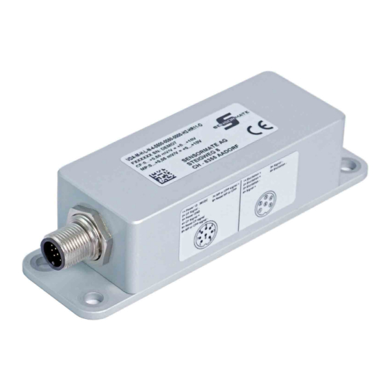
1. GENERAL DESCRIPTION 1.2. VDA-M Main features • Solution for: – Clamping Force measurement – Mold Protection – Cavity Pressure Profile monitoring • Only one sensor mounted either on the tie-bar or on the toggle • Usable on injection molding machines with toggle lever 1.2.1. -
Page 6: Installation
See Chapter ”5. Order Methods” on page 10 to check the configuration corresponding to each order code. Attention! If even one of the requirements mentioned above (trained technician in, device in perfect condition, correct configuration) is not satisfied, interrupt the installation and contact your Gefran dealer or Gefran Customer Service. 2.1. -
Page 7: Connection Diagrams
2. INSTALLATION 2.3. Connection Diagrams 2.3.1. Electrical Connection Sensor Side Sensor 4/4 bridge M16 6-pin Connector Excitation + Function Excitation + Excitation + Signal + Excitation - Signal + Signal - Excitation - Excitation - Signal - 2.3.2. Electrical Connection PLC Side PLC M12 8-pin Connector Function... -
Page 8: Operation
Wait 10 seconds (this is NOT used during manufacturing, 100% of the mold clamping force. just set-up). You can convert from με to tons / kN with the Gefran QE1008 Reset again (signal is now zero and stable). measurement system. -
Page 9: Molding Cycle
3. OPERATION 3.4. Molding Cycle Closing Mold protection Mold clamping Injection Opening Reset CF Reset MP Reset CP Attention! The duration of the various cycle steps is off-scale. Deactivate Reset CF before mold closing. Deactivate Reset MP just before the mold is clamped. Deactivate Reset CP after the mold is completely clamped and before starting injection. -
Page 10: Technical Data
4. TECHNICAL DATA TECHNICAL DATA 4.1. VDA-M Clamping force output Mold protection output Cavity pressure profile (CF) (MP) output (CPP) Linearity < ± 0.02% FS < ± 0.02% FS < ± 0.02% FS Output signal Voltage Accuracy at room temperature <... -
Page 11: Order Methods
The sensors are special versions of the GE1029 (bar strain sensor) and SB46 (press-on strain sensor). The SB46 sensor is applicable only on the toggle, and therefore does not measure the cavity pressure profile. Please contact Gefran for information on compatibility with other sensors. 5.3. -
Page 12: Operating Principles
Instead, the Gefran solution employs a single sensor whose length of 1 μm per meter, it is clear that this value changes signal is amplified by a variable amplifier to satisfy the various considerably during the various steps of the molding cycle. -
Page 13: Ideal Molding Cycle
6. OPERATING PRINCIPLES 6.3. Ideal Molding Cycle For every molding machine and every type of production, the This profile is the sum of the profiles of all the steps needed molding cycle can be represented as a continuous variation to complete the molding cycle. of the force applied to the mold as a function of time. - Page 14 GEFRAN spa via Sebina, 74 25050 Provaglio d’Iseo (BS) Italy Tel. +39 0309888.1 Fax +39 0309839063 info@gefran.com http://www.gefran.com...
Need help?
Do you have a question about the VDA-M and is the answer not in the manual?
Questions and answers