
Related Manuals for Rockwell Automation Sensia Qrate Scanner 3100


Summary of Contents for Rockwell Automation Sensia Qrate Scanner 3100
- Page 1 QRATE Scanner 3100 Integrated Control Flow Computer Installation, Operation & Maintenance Manual Manual No. 2350759-01, Rev. 6...
-
Page 2: Important Safety Information
QRATE Scanner 3100 Integrated Control Flow Computer Important Safety Information Symbols and Terms Used in this Manual Identifies information about practices or circumstances that can lead to personal WARNING injury or death, property damage, or economic loss. Un avertissement identifie des informations sur des pratiques ou des circonstances pouvant entraîner des blessures corporelles ou la mort, des dommages matériels ou AVERTISSEMENT des pertes économiques. -
Page 3: Table Of Contents
QRATE Scanner 3100 Integrated Control Flow Computer Table of Contents Table of Contents Important Safety Information ..............................ii Section 1—Introduction ........................... 1 About the QRATE Scanner 3100 integrated control flow computer ..................1 Web Browser-Based Interface ............................1 Supporting Software and User Help Documents......................1 Standard Features ..................................2 Product Identification ................................2 Hardware Options...................................3... - Page 4 Table of Contents QRATE Scanner 3100 Integrated Control Flow Computer Measuring Liquid via a Differential Pressure Meter ......................47 Best Practices ................................47 Direct Mount to Orifice Meter or Cone Meter ........................48 Remote Mount to Orifice Meter or Cone Meter ......................49 Measuring Compensated Liquid via a Turbine Meter ......................51 Best Practices ................................51 Performing a Manifold Leak Test ............................52 Zero Offset (Static Pressure or Differential Pressure) ......................52...
-
Page 5: About The Qrate Scanner 3100 Integrated Control Flow Computer
QRATE Scanner 3100 Integrated Control Flow Computer Table of Contents Section 6—QRATE Scanner 3100 Maintenance ................... 87 Lithium Battery Pack Replacement ............................87 Replacement Procedure..............................88 Section 7—QRATE Scanner 3100 Parts ....................... 89 Spare Parts and Optional Hardware.............................89 Table 7.1—QRATE Scanner 3100 integrated control flow computer Parts ..............89 Table 7.2—Wireless Components ..........................91 Table 7.3—RTD and Cable Assemblies ........................92 Electronics Replacement ..............................92... - Page 6 Table of Contents QRATE Scanner 3100 Integrated Control Flow Computer This page intentionally left blank.
-
Page 7: Section 1-Introduction
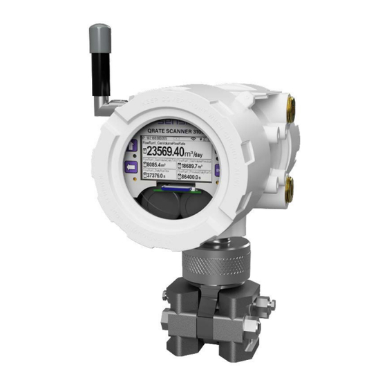
QRATE Scanner 3100 Integrated Control Flow Computer Section 1 Section 1—Introduction About the QRATE Scanner 3100 integrated control flow computer The QRATE Scanner* 3100 integrated control flow computer is uniquely designed to serve as a stand-alone flow computer or as a network manager capable of collecting and storing data from up to 20 NUFLO Scan- ner 2000 Series flow computers. -
Page 8: Standard Features
Section 1 QRATE Scanner 3100 Integrated Control Flow Computer Standard Features The QRATE Scanner 3100 features a double-ended explosion-proof enclosure with four conduit openings for inputs/outputs, a bottom conduit opening for a sensor, a large digital display, and a four-button keypad. Re- moving the front windowed cover provides access to batteries and the keypad. -
Page 9: Hardware Options
QRATE Scanner 3100 Integrated Control Flow Computer Section 1 Hardware Options The following hardware options are available for customizing the QRATE Scanner 3100 to your specific needs: sensors, battery packs, explosion-proof control switches, explosion-proof RTD assemblies, pole- mounting kits, and wireless communication components. See the sections below for details. Sensors The QRATE Scanner 3100 is available with no sensor or with an integral MVT (Figure... -
Page 10: Explosion-Proof Control Switch
Section 1 QRATE Scanner 3100 Integrated Control Flow Computer EXPLOSION RISK. Housing temperature must not exceed 70 °C (158 °F). Excessive tem- WARNING peratures, which could result from ambient conditions combined with radiated and conduc- tive heat from the process, could cause the internal lithium battery to ignite or explode. Each stick-style battery pack contains two 3.6 V batteries. -
Page 11: Explosion-Proof Rtd Assembly
QRATE Scanner 3100 Integrated Control Flow Computer Section 1 Control switches are wired and pre-configured at the factory (Figure 1.5) when they are purchased with the device. However, you can change the configuration via the web interface. A momentary switch is connected to DIO Terminal 5 at the factory, and a toggle switch is connected to DIO Terminal 6. -
Page 12: Flameproof Rtd Assembly (Atex, Zone 1)
Section 1 QRATE Scanner 3100 Integrated Control Flow Computer Cable length Probe length Figure 1.6—Explosion-proof (Class I, Div. 1) RTD assembly Flameproof RTD Assembly (ATEX, Zone 1) Sensia offers a flameproof RTD that is ATEX-certified for use in Zone 1 installations. The 4-wire, Class A sen- sor is encapsulated in a stainless steel sheath long enough to accommodate line sizes from 2 to 12 inches. -
Page 13: Wireless Communications
QRATE Scanner 3100 Integrated Control Flow Computer Section 1 Wireless Communications The QRATE Scanner 3100 wireless communications option includes factory-installed WiFi and SmartMesh wireless radio modules and couplers (Figure 1.8) that enables an external antenna to be safely used in a haz- ardous area. -
Page 14: Restricting The Configuration
Section 1 QRATE Scanner 3100 Integrated Control Flow Computer Mounting hardware supplied with Optional hardware kit for mounting the the Sensia remote-mount antenna Sensia remote-mount antenna to a (fits pole outside diameters up to 2 inches) 2-in. pipe (fits outside diameter of 2 3/8-in.) Figure 1.9—SmartMesh remote-mount antenna mounting options Restricting the Configuration It may be necessary to lock the configuration so that there cannot be any changes made. -
Page 15: Physical Configuration Lock Switch
QRATE Scanner 3100 Integrated Control Flow Computer Section 1 2. The menu will appear. Click to navigate to the ADMINISTRATION SECURITY SECURITY menu (see Figure 1.11). CONFIGURATION Figure 1.11—QRATE Scanner 3100 Web Interface Administration menu 3. The menu will appear. Click button and then click button beside Configuration Lock SECURITY MODIFY... - Page 16 Section 1 QRATE Scanner 3100 Integrated Control Flow Computer 4. The Configuration Lock Mode will appear (see Figure 1.13). Figure 1.13—QRATE Scanner 3100 Web Interface Configuration Lock Mode The configuration locking modes are as follows: Disabled. - Regardless of the position of the Physical Configuration Lock switch, the configuration •...
- Page 17 QRATE Scanner 3100 Integrated Control Flow Computer Section 1 Note For Secured Configuration (Category 3): Verification Triggering Events (VTEs) are enabled, and will show on the LCD if there is a change to a legally relevant metrological parameter. User changes will be restricted when the User Event log becomes nearly full, and the event records must be downloaded to allow further changes.
- Page 18 Section 1 QRATE Scanner 3100 Integrated Control Flow Computer The position of the Physical Configuration Lock switch may be verified (i.e. that the switch has been fully engaged) by observing the LCD display. When the switch has been fully engaged a Lock Glyph will be dis- played.
-
Page 19: Specifications
QRATE Scanner 3100 Integrated Control Flow Computer Section 1 Specifications Table 1.1—General Specifications CSA (US and Canada) Approvals Class I, Div. 1, Groups C and D, T4; Type 4 enclosure ATEX 15ATEX1122X— Ex d [ia Ga] ib IIC T5 Gb (Tamb –40 °C to 70 °C; –40 °F to 158 °F) IECEx SIR 15.0049X—... - Page 20 Section 1 QRATE Scanner 3100 Integrated Control Flow Computer Table 1.1—General Specifications Turbine meter Supported Meter Types Cone meter Orifice meter Ultrasonic meter Positive displacement (PD) meter Coriolis meter Venturi meter Complete (all records, including slave device records as Download Types Per Device applicable) Local (integral flow records in a condensed file ideal for...
- Page 21 QRATE Scanner 3100 Integrated Control Flow Computer Section 1 Table 1.1—General Specifications One RJ-45 connection supports two TCP/IP user-configurable Communications/ Ethernet/TCP ports with selectable slave protocols Archive Retrieval (cont’d) Continuous use requires external power Supports 10/100 Mbits/second Any communications port can be routed to another port Port Pass-Through Ethernet can be bridged to serial communications for remotely interfacing with connected Modbus devices.
- Page 22 Section 1 QRATE Scanner 3100 Integrated Control Flow Computer Table 1.1—General Specifications ± 0.05% of range for all except for 30 “H2O MVT Accuracy Differential Pressure ± 0.1% of range for 30 “H2O ± 0.05% of range Static Pressure ± 0.25% of full scale over operating range Temperature Effect Less than ±...
- Page 23 QRATE Scanner 3100 Integrated Control Flow Computer Section 1 Table 1.1—General Specifications 2 channels RTD Inputs 100-ohm platinum RTD with 2-wire, 3-wire, or 4-wire interface Range: –40 °C to 427 °C (–40 °F to 800 °F), excluding RTD uncertainty Accuracy: ± 0.2 °C (0.36 °F) over sensing range at calibrated temperature Temperature effect: ±...
- Page 24 Section 1 QRATE Scanner 3100 Integrated Control Flow Computer Table 1.1—General Specifications Release triggered archive latch Digital I/O Special Functions (cont’d) (cont’d) Create partial archive Abort script program Reset script program Output Modes Pulse (based on pulse count or time period) Alarm (based on the status of any or all selected alarms;...
- Page 25 QRATE Scanner 3100 Integrated Control Flow Computer Section 1 Table 1.2—Hardware Options 2.4 GHz self-healing and self-sustaining network Wireless SmartMesh Radio Factory installed with stainless steel, explosion-proof antenna coupler, N female × 3/4 MNPT, with 12-in. coaxial cable and MMCX male connector Transmits up to 300 m (985 ft) node-to-node Supports communications with up to 20 remote NUFLO Scanner 2000 Series devices (each Scanner node can transmit and receive data)
-
Page 26: Flow Rate And Fluid Property Calculations
Section 1 QRATE Scanner 3100 Integrated Control Flow Computer Table 1.2—Hardware Options 4-wire, 100-ohm explosion-proof RTD assembly suitable for CSA Class 1, Div. 1 installations RTD Temperature Sensor 4-wire, Class A sensor encapsulated by a stainless steel sheath and attached to a 3500 mm (11.48 ft) armoured cable Nominal 6.6 mm (0.26 in.) bore, 1/2-in. - Page 27 QRATE Scanner 3100 Integrated Control Flow Computer Section 1 Table 1.4—Flow Rate Standards Standard Description ♦ The QRATE Scanner 3100 supports the orifice metering calculations described AGA 3 (1992) in AGA Report No. 3 (1992). This meter covers pipe sizes of nominal 2-in. and larger;...
- Page 28 Section 1 QRATE Scanner 3100 Integrated Control Flow Computer Table 1.5—Fluid Property and Energy Flow Calculations Standard Description ♦ ♦ AGA 5 (2009) AGA 5 provides the methods for computing the mass, molar, and volumetric heating values of natural gas at reference temperature. AGA 5 is also used in calculating re- lated properties, including Wobbe index, motor octane number, and net (inferior) vol- ume heating value.
- Page 29 QRATE Scanner 3100 Integrated Control Flow Computer Section 1 Table 1.5—Fluid Property and Energy Flow Calculations Standard Description ♦ ISO 6976 specifies methods for the calculation of the superior calorific value and the ISO 6976 (2016) inferior calorific value, density, relative density and Wobbe index of dry natural gas and other combustible gaseous fuels, when the composition of the gas by mole frac- tion is known.
- Page 30 Section 1 QRATE Scanner 3100 Integrated Control Flow Computer Table 1.6—Flow Correction Factors Flow Correction Factor Description The multipoint meter factor calibration method allows users to compensate for Multipoint Meter Factor Correction (for Gas and variations between calibrations without changing the meter K-factor from the value Liquid) stamped on the meter at the factory.
-
Page 31: Section 2-Installing The Qrate Scanner 3100
QRATE Scanner 3100 Integrated Control Flow Computer Section 2 Section 2—Installing the QRATE Scanner 3100 Overview The QRATE QRATE Scanner 3100 Integrated Control Flow Computer is fully assembled at the time of ship- ment and ready for mounting. However, Sensia recommends that operators configure the device prior to mounting if the instrument is to be installed in a hazardous area. -
Page 32: Csa Installations
Section 2 QRATE Scanner 3100 Integrated Control Flow Computer CSA Installations The QRATE Scanner 3100 is CSA-certified as explosion-proof for Class I, Division 1, Groups C and D hazard- ous locations. Wiring Precautions All field wiring must conform to the National Electrical Code, NFPA 70, Article 501-4(b) for CAUTION installations within the United States or the Canadian Electric Code for installations within Canada. -
Page 33: Thermowell Location (For Gas And Liquid Flow Runs Only)
QRATE Scanner 3100 Integrated Control Flow Computer Section 2 Thermowell Location (for Gas and Liquid Flow Runs Only) The process temperature input is typically supplied by an RTD installed in a thermowell downstream of the primary differential pressure source using a 2-wire, 3-wire, or 4-wire RTD assembly. To ensure accurate mea- surement, the location of the thermowell should conform to the appropriate standard. -
Page 34: Pole-Mounting The Qrate Scanner 3100
Section 2 QRATE Scanner 3100 Integrated Control Flow Computer The following accessories are also recommended: • 5-valve manifold for connecting process lines to the MVT • RTD assembly for process temperature input on gas flow runs and compensated liquid flow runs •... -
Page 35: Hazardous Area Requirements For Wifi And Wireless Communications
QRATE Scanner 3100 Integrated Control Flow Computer Section 2 Install as follows: 1. Locate the mounting bosses on the side of the enclosure. 2. Attach the mounting bracket to the bosses using the four 10-mm screws provided. For best stability, orient the bracket so that the flat surface of the “L”... -
Page 36: Fcc Radio Frequency Compliance
Section 2 QRATE Scanner 3100 Integrated Control Flow Computer N-MALE CONNECTOR DIRECT-MOUNT ANTENNA PART NO. 2350869-01 CONNECTS TO WIRELESS MODULE INSIDE QRATE SCANNER 3100 ENCLOSURE N-FEMALE CONNECTOR ANTENNA COUPLER (NO SEAL REQUIRED) PART NO. 2350765-01 (CSA - NORTH AMERICA) PART NO. 77012876 (CSA - NORTH AMERICA and ATEX) PART NO. -
Page 37: Ic Radio Frequency Compliance
QRATE Scanner 3100 Integrated Control Flow Computer Section 2 interference in a residential installation. This equipment generates, uses and can radiate radio frequency en- ergy and, if not installed and used in accordance with the instructions, may cause harmful interference to ra- dio communications. -
Page 38: Antenna Installation Options
Section 2 QRATE Scanner 3100 Integrated Control Flow Computer Antenna Installation Options Direct-Mount Antenna Each QRATE Scanner 3100 wireless device is equipped with a wireless module (installed on an advanced communications circuit board) and an explosion-proof coupler that threads into an enclosure port. Antennas and antenna cable are optionally available (WiFi may use internal or external antenna). -
Page 39: Remote-Mount Antenna For Pipe Outside Diameters Of 2 3/8 Inches
QRATE Scanner 3100 Integrated Control Flow Computer Section 2 Remote-Mount Antenna for Pipe Outside Diameters of 2 3/8 Inches Sensia’s optional pipe mount kit accommodates mounting the remote antenna to a 2-in. pipe with a 2 3/8-in. outside diameter. The hardware kit includes a stainless steel L-shaped bracket, two U-bolts, four U-bolt nuts, two stainless steel 5/16-18 bolts (3.25-in. -
Page 40: Industry Standard Compliance
Section 2 QRATE Scanner 3100 Integrated Control Flow Computer Industry Standard Compliance To ensure measurement accuracy, flow runs and turbine meter runs must be installed in accordance with the industry standards listed in Table 2.2—Industry Standards for Meter Installation. For a complete list of indus- try standards used in the development of flow rate and fluid property calculations, see Table 1.4—Flow Rate Standards, page 21... - Page 41 QRATE Scanner 3100 Integrated Control Flow Computer Section 2 Table 2.2—Industry Standards for Meter Installation Meter Type Standard Description Installation of orifice plates inserted into a circular cross-section conduit Venturi Meter ISO 5167, Part 1 running full Limitation of pipe size and Reynolds number ISO 5167 is applicable only to flow that remains subsonic throughout the measuring section and where the fluid can be considered single-phase.
-
Page 42: Measuring Natural Gas Via A Differential Pressure Meter
Section 2 QRATE Scanner 3100 Integrated Control Flow Computer Measuring Natural Gas via a Differential Pressure Meter Best Practices For best measurement accuracy, ensure that the meter run complies with the following AGA 3 and ISO 5167 guidelines, as applicable: •... -
Page 43: Direct Mount To Orifice Meter Or Cone Meter
QRATE Scanner 3100 Integrated Control Flow Computer Section 2 Direct Mount to Orifice Meter or Cone Meter A QRATE Scanner 3100 can be mounted directly to an orifice meter or cone meter for gas measurement. The setup of the meter run and plumbing configurations can vary widely, depending upon the challenges existing on location. -
Page 44: Remote Mount To Orifice Meter Or Cone Meter
Section 2 QRATE Scanner 3100 Integrated Control Flow Computer 5. Route any additional inputs/outputs or COM connections, etc. through a conduit opening in the top of the enclosure. For hazardous areas, review Hazardous Area Precautions, page 6. Perform a manifold leak test as described in Performing a Manifold Leak Test, page 7. -
Page 45: Measuring Natural Gas Via A Turbine Meter
QRATE Scanner 3100 Integrated Control Flow Computer Section 2 8. Verify the zero offset (if required) and other calibration points (if desired). See the QRATE Scanner 3100 Web Interface User Manual for complete instructions. See also Zero Offset (Static Pressure or Differential Pressure), page Differential Pressure Calibration and Verification, page 52, and... -
Page 46: Remote Mount To A Turbine Meter
Section 2 QRATE Scanner 3100 Integrated Control Flow Computer Remote Mount to a Turbine Meter A QRATE Scanner 3100 can be mounted remotely and connected to a gas turbine meter for measuring gas in accordance with AGA 7 calculations. Figure 2.11, page 41 shows an installation in which the pressure input is provided by the integral MVT. -
Page 47: Measuring Steam Via A Differential Pressure Meter
QRATE Scanner 3100 Integrated Control Flow Computer Section 2 Seal cable at point of entry in accordance with the relevant code of practice Manifold assembly Flow Static pressure input (manifold equalizer valve must remain open) 5 pipe diameters 10 pipe diameters downstream upstream Figure 2.11—Remote-mount installation in an AGA 7 turbine meter run... -
Page 48: Installation Procedure-Remote Mount To Orifice Meter Or Cone Meter
Section 2 QRATE Scanner 3100 Integrated Control Flow Computer Hot Legs • Hot legs should be large diameter (1/2 in. recommended) • Hot legs should be as short as possible. If these sections must be more than 1ft in length, insulate them. •... - Page 49 QRATE Scanner 3100 Integrated Control Flow Computer Section 2 Pipe tee (can be used to fill cold legs) Condensate pot (pipe tee with blowdown valve attached) Long cold legs protect the sensor from extreme process temperatures Hot legs, insulated to within Cold legs connect to manifold 1 ft of condensate pot (slope to eliminate air trap)
- Page 50 Section 2 QRATE Scanner 3100 Integrated Control Flow Computer 4. Install a pipe cap or a blowdown valve that is rated for steam service at the top of each pipe tee. A blow- down valve is recommended when the steam passing through the meter is known to be dirty. 5.
-
Page 51: Measuring Liquid Via A Differential Pressure Meter
QRATE Scanner 3100 Integrated Control Flow Computer Section 2 Measuring Liquid via a Differential Pressure Meter Best Practices To ensure measurement accuracy, ensure that the meter run complies with the following AGA 3 and ISO 5167 guidelines, as applicable: • Do not place unit near vents or bleed holes that discharge corrosive vapors or gases. -
Page 52: Direct Mount To Orifice Meter Or Cone Meter
Section 2 QRATE Scanner 3100 Integrated Control Flow Computer • Install shutoff valves directly on the pressure taps. Choose a shutoff valve that is rated for the ambient temperatures of the location and the operating pressure of the pipe in which it will be installed, and for use with dangerous or corrosive fluids or gases, if applicable. -
Page 53: Remote Mount To Orifice Meter Or Cone Meter
QRATE Scanner 3100 Integrated Control Flow Computer Section 2 MVT with side ports Block Adapter manifold (2 typ.) Figure 2.13—Direct-mount liquid cone meter run installation. The downstream RTD is not shown. Remote Mount to Orifice Meter or Cone Meter A QRATE Scanner 3100 can be mounted remotely and connected to an orifice meter or cone meter with tub- ing for liquid measurement (Figure 2.14, page 48). - Page 54 Section 2 QRATE Scanner 3100 Integrated Control Flow Computer 4. Install the RTD assembly in the thermowell. Remove the plug from a conduit opening in the top of the en- closure, route the RTD assembly cable through the conduit opening and connect it to the terminal board. A wiring diagram for the RTD assembly is provided in Figure 3.6, page 59.
-
Page 55: Measuring Compensated Liquid Via A Turbine Meter
QRATE Scanner 3100 Integrated Control Flow Computer Section 2 b. Open the equalizer and bypass/block valves on the block manifold. Make sure the vent valve is closed. c. Open one of the shut-off valves near the meter. d. Slowly loosen the corresponding vent screw on the MVT, and throttle the rate of flow from the vent with the shut-off valve. -
Page 56: Performing A Manifold Leak Test
Section 2 QRATE Scanner 3100 Integrated Control Flow Computer Performing a Manifold Leak Test A manifold leak test is recommended prior to operating any differential pressure meter into service. Check the manifold for leaks as follows: 1. Verify that the instrument is approximately level and is properly connected to the pressure source. 2. -
Page 57: Static Pressure Calibration And Verification
QRATE Scanner 3100 Integrated Control Flow Computer Section 2 6. Click to exit the dialog. The measured zero offset will be displayed on the screen. Accept 7. Click to apply the offset to the device, and exit the Maintenance mode. Save Note Zero offset values are cleared when a new calibration is saved. -
Page 58: Differential Pressure Calibration And Verification
Section 2 QRATE Scanner 3100 Integrated Control Flow Computer EQUALIZER EQUALIZER VENT BYPASS/ BYPASS/ BLOCK BLOCK Figure 2.17—Valve positions for static pressure calibration To verify the static pressure, perform the steps described in steps 6 through 12 above, except instead of click- ing the tab, click the tab. -
Page 59: Placing The Scanner Into Operation
QRATE Scanner 3100 Integrated Control Flow Computer Section 2 EQUALIZER EQUALIZER VENT BYPASS/ BYPASS/ BLOCK BLOCK Figure 2.18—Valve positions for differential pressure calibration To verify the differential pressure, perform the steps described in steps 6 through 12 above, except instead of clicking the tab, click the tab. - Page 60 Section 2 QRATE Scanner 3100 Integrated Control Flow Computer This page intentionally left blank.
-
Page 61: Section 3-Wiring The Qrate Scanner 3100
QRATE Scanner 3100 Integrated Control Flow Computer Section 3 Section 3—Wiring the QRATE Scanner 3100 Field Wiring Connections Do not connect/disconnect equipment or change batteries unless the area is known to be WARNING non-hazardous. The QRATE Scanner 3100 poses no hazard when opened in a safe area. All field wiring must conform to the National Electrical Code, NFPA 70, Article 501-4(b) for CAUTION installations within the United States or the Canadian Electric Code for installations within... - Page 62 Section 3 QRATE Scanner 3100 Integrated Control Flow Computer Ground screws Ground screw (located on side of enclosure) Figure 3.2—External and internal ground screw locations c. Connect the flowmeter input wiring to TFM 1, TFM 2, or TFM 3, as required. Terminal Block Terminals TFM 1...
-
Page 63: Power Supply Wiring
QRATE Scanner 3100 Integrated Control Flow Computer Section 3 Power Supply Wiring Internal Power Supply Sensia’s 7.2 V lithium battery packs provide reliable backup power when used with an external primary power supply. The QRATE Scanner 3100 supports up to two battery packs simultaneously. The battery compartment is lo- cated below the display/keypad assembly and is readily accessible when the front cover is removed from the enclosure. -
Page 64: External Power Supply
Section 3 QRATE Scanner 3100 Integrated Control Flow Computer Battery Life Although external power is recommended for continuous use, the dual battery packs will autonomously power the QRATE Scanner 3100 for an estimated 2 to 3 weeks under a base load (no analog inputs, digital outputs, or Ethernet communication). -
Page 65: Input Wiring
QRATE Scanner 3100 Integrated Control Flow Computer Section 3 Input Wiring Turbine Flowmeter Inputs TFM inputs 1, 2 and 3 on the terminal board provide the turbine flowmeter input signal generated by a mag- netic pickup, enabling the QRATE Scanner 3100 to calculate and display instantaneous flow rates and accu- mulated totals. -
Page 66: Analog Inputs
Section 3 QRATE Scanner 3100 Integrated Control Flow Computer Analog Inputs The analog inputs (Figure 3.7), which can be configured for a 0 to 5 V, 1 to 5 V, 0 to 20 mA or 4 to 20 mA sig- nal, can be used to receive readings from a pressure or temperature transmitter for use in any flow run. -
Page 67: Digital Inputs-Contact Closure
QRATE Scanner 3100 Integrated Control Flow Computer Section 3 Digital Inputs—Contact Closure The digital contact closure input (Figure 3.9, top) provides an input for use with any relay contact switch. DIO 1 through DIO 4 are optically isolated. DIO 5 and DIO 6 (Figure 3.9, bottom) are non-isolated. -
Page 68: Digital Inputs-Pulse
Section 3 QRATE Scanner 3100 Integrated Control Flow Computer Digital Inputs—Pulse The digital pulse input (Figure 3.10) provides an input for use with any 3 to 30 VDC pulse-generating device. DIOs 1 through 4 (shown at left) are optically isolated. DIOs 5 and 6 (shown at right) are non-isolated. To configure a pulse input using the web interface, choose as the input type, and select a trigger state Pulse... -
Page 69: Output Wiring
QRATE Scanner 3100 Integrated Control Flow Computer Section 3 Output Wiring Analog (4 to 20 mA) Outputs The 4 to 20 mA output (Figure 3.12) provides a linear current output that can be configured to represent any parameter in the holding registers using the QRATE Scanner 3100 web interface. This output requires a two- conductor cable connected to a 9 to 30 VDC power supply (voltage required is dependent on loop resistance) and a current readout device located in the remote location. -
Page 70: Digital Outputs
Section 3 QRATE Scanner 3100 Integrated Control Flow Computer Digital Outputs The standard QRATE Scanner 3100 supports six solid-state digital outputs that are configurable as pulse out- puts, alarm outputs, conditional outputs, or programmed outputs using time of day or an output state as the trigger. -
Page 71: Communications
QRATE Scanner 3100 Integrated Control Flow Computer Section 3 Communications RS-485 Communications The QRATE Scanner 3100 supports digital serial communications using EIA-RS-485 hardware with Modicon Modbus protocol. RS-485 communications are supported by three ports with a baud range of 300 to 115.2K. Ports 1, 2, and 3 can be used simultaneously, if desired, and all three ports are protected from high-voltage transients. -
Page 72: Ethernet Communications
Section 3 QRATE Scanner 3100 Integrated Control Flow Computer Ethernet Communications An RJ-45 connector (Figure 3.1, page 55) provides the Ethernet communications required for accessing the web interface via a web browser and for transmitting data over two TCP ports. The TCP ports support Modbus TCP and Modbus-over-TCP protocols and can be configured individually (assigned to unique port numbers) using the web interface. -
Page 73: Section 4-Connecting To The Qrate Scanner 3100 Web Interface
QRATE Scanner 3100 Integrated Control Flow Computer Section 4 Section 4—Connecting to the QRATE Scanner 3100 Web Inter- face To connect to the QRATE Scanner 3100 interface, you will need to establish a local area network between your computer (PC or laptop) and the Scanner using Ethernet cables and possibly, a router. An IP address will be assigned to the device during this process. -
Page 74: Connection Options
Section 4 QRATE Scanner 3100 Integrated Control Flow Computer Connection Options A computer can be connected to a QRATE Scanner 3100 using either of two methods: • This method is recommended only if you have experience Direct (1 to 1) Connection (Ethernet Only). changing Windows settings and have the administrative rights to assign a static IP address to your computer. -
Page 75: Ad-Hoc Wireless Router Connection
QRATE Scanner 3100 Integrated Control Flow Computer Section 4 Ad-Hoc Wireless Router Connection If you have no wireless access point or work for a company that does not wish to add another device to the corporate Ethernet network, a portable wireless router can be used to establish a local area network. Routers with a single LAN port must be used with a wireless-enabled laptop. -
Page 76: Multi-Port Router Option
Section 4 QRATE Scanner 3100 Integrated Control Flow Computer d. Select Manually create a network profile e. Enter the wireless network information recorded in step 4c. Select and click Start this connection automatically Next 6. Click the “Wireless Communication” icon on the Quick Access tray at the bottom of the laptop screen. If you cannot see the icon, expand the Quick Access tray. -
Page 77: Wifi Communications Accessory
QRATE Scanner 3100 Integrated Control Flow Computer Section 4 WiFi Communications Accessory The WiFi communications accessory (“WiFi box”) provides wireless access to the QRATE Scanner 3100 via the web interface and a permanently installed wireless modem. The WiFi box is externally powered and can be accessed by multiple users. - Page 78 Section 4 QRATE Scanner 3100 Integrated Control Flow Computer Pole Mount To mount the WiFi box on a vertical pipe or pole, osition the U-bolts around the pipe and secure them to the integral brackets on the WiFi box using the nuts provided (Figure 4.2).
-
Page 79: Wiring The Wifi Box
QRATE Scanner 3100 Integrated Control Flow Computer Section 4 2. Position the U-bolts around the pipe and secure to the mounting bracket with the nuts provided. Figure 4.3—(Left) Standard antenna mounting bracket for outside pipe diameters up to 2-in. and (right) alternate antenna mounting bracket for outside pipe diameters of 2.375-in. - Page 80 Section 4 QRATE Scanner 3100 Integrated Control Flow Computer To wire the WiFi box for operation, perform the following steps: 1. Open the door of the WiFi box and open the F1 and F2 fuse housings on the power block (Figure 4.5).
- Page 81 QRATE Scanner 3100 Integrated Control Flow Computer Section 4 e. To free up space for pulling wires through the conduit port, unseat the terminal board by unscrewing the four Phillips screws holding it in place and gently pulling the board straight back to disconnect it from its connected header without bending pins.
- Page 82 Section 4 QRATE Scanner 3100 Integrated Control Flow Computer a. Thread the external power supply wires through the conduit hub on the bottom of the WiFi box (Figure 4.4, page 73). b. Tighten the power supply cable connector. c. Verify that the F1 and F2 fuse housings on the power block are open (Figure 4.8, page 75).
-
Page 83: Connecting To The Qrate Scanner 3100
QRATE Scanner 3100 Integrated Control Flow Computer Section 4 Connecting to the QRATE Scanner 3100 The WiFi modem is pre-configured at the factory to expedite user setup in the field. To connect to the QRATE Scanner 3100 web interface via the WiFi accessory, 1. - Page 84 Section 4 QRATE Scanner 3100 Integrated Control Flow Computer This page intentionally left blank.
-
Page 85: Section 5-Display And Keypad Operations
QRATE Scanner 3100 Integrated Control Flow Computer Section 5 Section 5—Display and Keypad Operations The QRATE Scanner 3100 display and keypad allows you to view the real-time measurements for up to 32 selected parameters, 5 at a time. By default, the parameters scroll continuously through the 5 fields provided (Figure 5.1). - Page 86 Section 5 QRATE Scanner 3100 Integrated Control Flow Computer Table 5.1—Device Status Glyph Definitions Keypad Use. This glyph depicts the four keys positioned on either side of the LCD. Pressing a key on the keypad causes the corresponding key in the glyph to appear filled, verifying that the key is actuated.
-
Page 87: Configurable Display Features
QRATE Scanner 3100 Integrated Control Flow Computer Section 5 Table 5.1—Device Status Glyph Definitions Wireless Communications Status. The wireless transmitter is disabled. No mesh nodes are configured. At least one mesh node is configured but none are operational. One or more mesh nodes are configured and at least one is operational. Multiple mesh nodes are configured and all are operational. -
Page 88: Message Display Mode
Section 5 QRATE Scanner 3100 Integrated Control Flow Computer Message Display Mode You can force selected “high priority” parameters to be displayed only in the top field of the display by assign- ing a priority status to these parameters (Figure 5.2). -
Page 89: Lcd Display Indicator
QRATE Scanner 3100 Integrated Control Flow Computer Section 5 LCD Display Indicator To change the LCD display view, leave the enclosure lid in place and cover the right side or left side of the LCD with your hand for 4 to 8 seconds, after which the device should detect your hand. Upon detection, the Scanner window will display a popup window with the device information. - Page 90 Section 5 QRATE Scanner 3100 Integrated Control Flow Computer This page intentionally left blank.
-
Page 91: Section 6-Qrate Scanner 3100 Maintenance
QRATE Scanner 3100 Integrated Control Flow Computer Section 6 Section 6—QRATE Scanner 3100 Maintenance The QRATE Scanner 3100 is engineered to provide years of dependable service with minimal maintenance. Batteries require periodic replacement, and battery life depends on (1) whether battery power is the primary or secondary power source, (2) the configuration settings of the device, and (3) ambient temperature condi- tions. -
Page 92: Replacement Procedure
Section 6 QRATE Scanner 3100 Integrated Control Flow Computer Replacement Procedure The stick-style battery packs are installed in a compartment just below the display (Figure 6.1). Battery leads are connected to the QRATE Scanner 3100 via two connectors extending from the back side of the display assembly on either side of the rounded cutout. -
Page 93: Section 7-Qrate Scanner 3100 Parts
QRATE Scanner 3100 Integrated Control Flow Computer Section 7 Section 7—QRATE Scanner 3100 Parts Spare Parts and Optional Hardware The stick-style lithium battery packs, the lithium coin cell battery that controls the real-time clock, and the des- iccant packets are the only consumable parts within the QRATE Scanner 3100 that require periodic replace- ment. - Page 94 Section 7 QRATE Scanner 3100 Integrated Control Flow Computer Table 7.1—QRATE Scanner 3100 integrated control flow computer Parts Qty. Part Number Description ATEX-Approved Parts 9A-X-TTXR-0003 Assembly, RTD and Cable, Flameproof, 3500-mm Cable, 50-mm Probe, ATEX-approved, for Line Sizes from 2 to 12 inches 50302004 Battery Pack, 2 D Batteries in Series, 7.2 V, Lithium, Stick Style, ATEX-approved 50302001...
- Page 95 QRATE Scanner 3100 Integrated Control Flow Computer Section 7 Table 7.2—Wireless Components Qty. Part No. Description 77012876 Antenna Coupler, N Coax, Male-to-Male (Female Thread), CSA & ATEX-approved 2350869-01 Antenna, Short-haul Wireless, 2.4 GHz, 1/2 Wave Dipole, N Male, Right-Angle 50279275 Antenna, Short-Haul Wireless, Remote-Mount, 9 dBi 2.4 GHz Omnidirectional, 32-in.
-
Page 96: Electronics Replacement
Section 7 QRATE Scanner 3100 Integrated Control Flow Computer Table 7.3—RTD and Cable Assemblies Select assemblies based on specific application. Cable length and probe length are specified in the part number: 9A-21-XX-YY where XX is the cable length and YY is the probe length. Available cable lengths: 5, 10, or 30 ft. -
Page 97: Appendix A-Lithium Battery Information
QRATE Scanner 3100 Integrated Control Flow Computer Appendix A Appendix A—Lithium Battery Information Lithium Battery Disposal Once a lithium battery is removed from a device and/or is destined for disposal, it is classified as solid waste under EPA guidelines. Depleted lithium batteries are also considered to be hazardous waste because they meet the definition of Reactivity, as per 40 CFR 261.23(a)(2), (3) and (5). - Page 98 Appendix A QRATE Scanner 3100 Integrated Control Flow Computer This page intentionally left blank.
-
Page 99: Appendix B-Ftp Downloads
QRATE S anner 3100 Integrated Control Flow Computer Appendix B Appendix B—FTP Downloads FTP downloads provide an alternative to the web interface download process and may be preferred for expe- diting downloads, particularly if you have no other need to log into the web interface. FTP downloads can be performed with a router connection to the Scanner, or with a physical Ethernet cable connection between the PC/laptop and the Scanner. -
Page 100: Slave Device Archive Logs
Appendix B QRATE Scanner 3100 Integrated Control Flow Computer Full Folder Contents Example Filename Daily Logs: QRATE Scanner 3100 S3100_FA01_D_Full.sdf Interval Logs: QRATE Scanner 3100 S3100_FA01_I_Full.sdf Triggered Logs: QRATE Scanner 3100 DeviceName_TR_Full.sdf Daily Logs: NUFLO Scanner 2000 series flow computers Slave01_SA01_D_Full.sdf configured as a slave device (up to 20 logs possible) Interval Logs: NUFLO Scanner 2000 series flow... -
Page 101: Appendix C-Firmware, Configuration, Scanner Logic, And Modbus Register Map Uploads
QRATE Scanner 3100 Integrated Control Flow Computer Appendix C Appendix C—Firmware, Configuration, Scanner Logic, and Modbus Register Map Uploads Firmware Uploads The factory default firmware is easily restored using the QRATE Scanner 3100 web interface. Simply log into the device interface, select from the taskbar, then click at the left ADMINISTRATION>GENERAL... -
Page 102: Scanflash Upload
Appendix C QRATE Scanner 3100 Integrated Control Flow Computer • To upload a register map via the web interface, log into the device interface, select ADMINISTRATION> from the taskbar and click at the left of the screen. To erase the map currently GENERAL Installed Files installed, click... - Page 103 QRATE Scanner 3100 Integrated Control Flow Computer Appendix C 8. Click to confirm the connection and identify the current firmware version. The button will turn blue Verify while the utility attempts to communicate with the Scanner. When a connection has been verified, the Scanner’s system information will appear in the Results log –...
- Page 104 Appendix C QRATE Scanner 3100 Integrated Control Flow Computer This page intentionally left blank.
-
Page 105: Appendix D-Measurement Canada Configuration
QRATE Scanner 3100 Integrated Control Flow Computer Appendix D Appendix D—Measurement Canada Configuration It is imperative that the device be installed as per the guidelines that have been articulated by Measurement Canada. Any explicit instructions or guidelines from Measurement Canada take precedence over the instruc- tions given in this manual. -
Page 106: Physical Configuration Lock Switch
Appendix D QRATE Scanner 3100 Integrated Control Flow Computer Physical Configuration Lock Switch The Physical Configuration Lock switch is located inside the QRATE Scanner 3100 housing along the top edge of the display circuit board assembly, just left of center (Figure D.1). - Page 107 QRATE Scanner 3100 Integrated Control Flow Computer Appendix D To access the software Configuration Lock Mode settings use the following steps: 1. Navigate to the menu by (see Figure D.3). ADMINISTRATION DEVICE>ADMINISTRATION>GENERAL Figure D.3—QRATE Scanner 3100 Web Interface directions to Device Status screen 2.
- Page 108 Appendix D QRATE Scanner 3100 Integrated Control Flow Computer 3. The menu will appear. Click button and then click button beside Configuration Lock SECURITY MODIFY Mode (see Figure D.5). Figure D.5—QRATE Scanner 3100 Web Interface Security menu 4. The Configuration Lock Mode will appear (see Figure D.6).
- Page 109 QRATE Scanner 3100 Integrated Control Flow Computer Appendix D For Measurement Canada, the Scanner must have firmware version: 3.040 - 3.069 Configuration Secured Seal Configuration (MC Category 2) (MC Category 3) Physical Configuration No Lock Glyph. No Lock Glyph Lock Configuration changes are permitted.
-
Page 110: Device Physical Sealing Methods
Appendix D QRATE Scanner 3100 Integrated Control Flow Computer Device Physical Sealing Methods After the configuration has been completed and the configuration lock switch has been engaged (set toward the front of the Scanner), then the lid may be replaced, and a seal is to be applied. For Measurement Canada, the sealing method is to intall a wire seal. -
Page 111: Exporting User Event Records
QRATE Scanner 3100 Integrated Control Flow Computer Appendix D Exporting User Event Records When the device is sealed with Secured Configuration (Category 3) mode, the user can continue to make changes via the Web Interface or Modbus Protocols if less than 1000 records unused or previously exported records remain. -
Page 112: Verification Triggering Events
Appendix D QRATE Scanner 3100 Integrated Control Flow Computer Verification Triggering Events While in Secured Configuration (Category 3) mode, the QRATE Scanner 3100 can be remotely and locally configured without breaking a physical seal. Configuration capability of the QRATE Scanner 3100 is con- trolled by the Physical Configuration Lock switch and a software switch. - Page 113 WARRANTY - LIMITATION OF LIABILITY: Seller warrants only title to the products, software, supplies and materials and that, except as to software, the same are free from defects in workmanship and materials for a period of one (1) year from the date of delivery. Seller does not warranty that software is free from error or that software will run in an uninterrupted fashion.
- Page 114 CONTACT US Regional Offices Telephone Alberta, Canada +1 587 291 2190 Duncan, OK +1 580 736 7600 Coraopolis, PA +1 724 218 7800 Midland, TX +1 432 247 6020 Tunbridge Wells, UK +44 1892 518000 Mexico +1 52 55 5246 2000 Toll-Free Support 1-866-7 SENSIA (+1 866 773 6742) Inquiries...
Need help?
Do you have a question about the Sensia Qrate Scanner 3100 and is the answer not in the manual?
Questions and answers