
Related Manuals for Rockwell Automation Allen-Bradley 1440-TBS-J


Summary of Contents for Rockwell Automation Allen-Bradley 1440-TBS-J
-
Page 1: Table Of Contents
Installation Instructions XM Dynamic Measurement Module Terminal Base Catalog Number 1440-TBS-J Topic Page Important User Information Environment and Enclosure North American Hazardous Location Approval European Hazardous Location Approval Prevent Electrostatic Discharge About the Terminal Base Before You Begin Power Requirements Wiring Requirements Grounding Requirements Terminating Resistors... -
Page 2: Important User Information
In no event will Rockwell Automation, Inc. be responsible or liable for indirect or consequential damages resulting from the use or application of this equipment. -
Page 3: Environment And Enclosure
XM Dynamic Measurement Module Terminal Base 3 Environment and Enclosure This equipment is intended for use in a Pollution Degree 2 industrial ATTENTION environment, in overvoltage Category II applications (as defined in IEC 60664-1), at altitudes up to 2000 m (6562 ft) without derating. This equipment is not intended for use in residential environments and may not provide adequate protection to radio communication services in such environments. -
Page 4: North American Hazardous Location Approval
4 XM Dynamic Measurement Module Terminal Base North American Hazardous Location Approval The following information applies when Informations sur l’utilisation de cet operating this equipment in hazardous équipement en environnements dangereux. locations. Products marked "CL I, DIV 2, GP A, B, C, D" are suitable for Les produits marqués "CL I, DIV 2, GP A, B, C, D"... -
Page 5: European Hazardous Location Approval
Zone 2 environments. This equipment must be used within its specified ratings defined by WARNING Rockwell Automation. Provision must be made to prevent the rated voltage from being exceeded by WARNING transient disturbances of more than 140% of the rated voltage when applied in Zone 2 environments. -
Page 6: Prevent Electrostatic Discharge
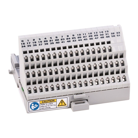
6 XM Dynamic Measurement Module Terminal Base This equipment must be used only with ATEX-certified Allen-Bradley WARNING backplanes. Secure any external connections that mate to this equipment by using screws, WARNING sliding latches, threaded connectors, or other means provided with this product. - Page 7 XM Dynamic Measurement Module Terminal Base 7 The 1440-TBS-J uses spring-clamp termination. 31882-M Component Identification Locking tab Keyswitch - set to the position required for the installed module Male XM Bus connector 96 pin female I/O connector Terminal base unit Locking tab 7, 8, 9 Terminal strips for connecting transducer wiring, common, power...
-
Page 8: Before You Begin
8 XM Dynamic Measurement Module Terminal Base Before You Begin To effectively use the terminal base, note the following considerations. Power Requirements Use a single Class 2 power supply to power the XM modules. Total current draw through the side connector cannot exceed 3 A. Refer to the specification for the specific modules for power requirements. -
Page 9: Wiring Requirements
XM Dynamic Measurement Module Terminal Base 9 Wiring Requirements Use solid or stranded wire. All XM wiring must meet the following specifications: • 2.1…0.34 mm² (22…14 AWG) copper conductors without pretreatment; 8.4 mm² (8 AWG) or 1 in. copper required for grounding the DIN rail for electromagnetic interference (EMI) purposes •... - Page 10 10 XM Dynamic Measurement Module Terminal Base DIN Rail Grounding Block To Earth Ground Din Rail Grounding Block 8.4 mm² (AWG 8) Wire Cat. No. 1492-WG10 24V Common Grounding The XM system is sourced by a single Class 2 power supply. We recommend grounding the 24V power to the XM modules.
-
Page 11: Terminating Resistors
XM Dynamic Measurement Module Terminal Base 11 Terminating Resistors The XM Bus operates correctly when there is a terminating resistor at each end of the XM Bus: • Terminating resistors must be 121Ω, 1%, 1/4 W. • When installing the XM ControlNet adapter with XM modules, the ControlNet adapter has an internal terminating resistor. -
Page 12: Install The Terminal Base
12 XM Dynamic Measurement Module Terminal Base Install the Terminal Base The terminal base can be DIN rail or wall/panel mounted. If you insert or remove the module while backplane power is on, an electrical WARNING arc can occur. This could cause an explosion in hazardous location installations. - Page 13 XM Dynamic Measurement Module Terminal Base 13 2. Slide the terminal base unit over leaving room for the side connector (B). 3. Hook the lip on the rear of the terminal base onto the top of the DIN rail, and rotate the terminal base onto the rail. 31883-M 4.
-
Page 14: Interconnect Terminal Base Units
14 XM Dynamic Measurement Module Terminal Base Interconnect Terminal Base Units Follow the steps below to install another terminal base unit. Terminal base units are mounted left to right on the DIN rail. IMPORTANT 1. Position the terminal base on the 35 x 7.5 mm DIN rail (A). 2. -
Page 15: Panel/Wall Mounting
XM Dynamic Measurement Module Terminal Base 15 Panel/Wall Mounting Installation on a wall or panel consists of: • laying out the drilling points on the wall or panel. • drilling the pilot holes for the mounting screws. • installing the terminal base units and securing them to the wall or panel. -
Page 16: Wiring
16 XM Dynamic Measurement Module Terminal Base 5. Position the terminal base unit up tight against the neighboring terminal base; make certain the hook on the terminal base slides under the edge of the terminal base unit. 6. Gently push the side connector into the side of the neighboring terminal base to complete the backplane connection. - Page 17 XM Dynamic Measurement Module Terminal Base 17 No. Desc. No. Desc. Desc. Xdcr 0 (+) Xdcr 1 (+) Tach (+) Xdcr 0 (-) Xdcr 1 (-) Tach (-) Functional Functional Functional Earth Earth Earth 24V (-) 24V (-) Tach 24V (-) 24V (+) 24V (+) Tach 24V (+)
-
Page 18: Specifications
18 XM Dynamic Measurement Module Terminal Base Specifications XM Dynamic Measurement Terminal Base - 1440-TBS-J Attribute Value Enclosure Type Rating None (open-style) Isolation Voltage Established by installed module Voltage Ratings XM Bus 24V DC, 3 A max, Class 2/SELV/PELV Power Terminals 24V DC, 3 A, Class 2/SELV/PELV I/O Terminals 24V DC, 60 mA, Class 2/SELV/PELV... - Page 19 XM Dynamic Measurement Module Terminal Base 19 Environmental Specifications Attribute Value Non-operating temperature -40…85 °C (-40…185 °F) IEC 60068-2-1 (Test Ab, Unpackaged Non-operating Cold), IEC 60068-2-2 (Test Bb, Unpackaged Non-operating Dry Heat), IEC 60068-2-14 (Test Na, Unpackaged Non-operating Thermal Shock): Relative humidity 5…95% noncondensing IEC 60068-2-30 (Test Db, Unpackaged Damp...
- Page 20 20 XM Dynamic Measurement Module Terminal Base Environmental Specifications Attribute Value Surge Transient Immunity ±1 kV line-line (DM) and ±2 kV line-earth IEC 61000-4-5: (CM) on power ports ±1 kV line-line (DM) and ±2 kV line-earth (CM) on signal ports ±2 kV line-earth (CM) on shielded ports Conducted RF Immunity 10V rms with 1 kHz sine-wave 80% AM...
- Page 21 XM Dynamic Measurement Module Terminal Base 21 Certifications Certifications (when product is marked) Description Korean Registration of Broadcasting and Communications Equipment, compliant with: • Article 58-2 of Radio Waves Act, Clause 3 See the Product Certification link at http://www.ab.com for Declarations of Conformity, Certificates, and other certification details.
-
Page 22: Additional Resources
Industrial Automation Wiring and Grounding Provides general guidelines for installing a Guidelines, publication 1770-4.1 Rockwell Automation® industrial system. Product Certifications website, Provides declarations of conformity, http://www.ab.com certificates, and other certification details. You can view or download publications at http://www.rockwellautomation.com/literature. - Page 23 XM Dynamic Measurement Module Terminal Base 23 Notes: Publication ICM-IN003D-EN-P - March 2013...
- Page 24 Rockwell Automation representative. New Product Satisfaction Return Rockwell Automation tests all of its products to ensure that they are fully operational when shipped from the manufacturing facility. However, if your product is not functioning and needs to be returned, follow these procedures.
Need help?
Do you have a question about the Allen-Bradley 1440-TBS-J and is the answer not in the manual?
Questions and answers