Table of Contents
Advertisement
Quick Links
Advertisement
Table of Contents

Related Manuals for Formula Air BADA000018


Summary of Contents for Formula Air BADA000018
- Page 1 BADA ATEX Non-Return Valve Maintenance Manual...
-
Page 2: Table Of Contents
Contents PRODUCT DESCRIPTION ........................2 How it works ..........................3 Overall dimensions ........................5 Technical datasheet ......................... 6 1.3.1 Push flow situation ......................6 1.3.2 Pull flow situation ......................6 1.3.3 Special conditions for safe use ..................6 INSTALLATION ..........................8 Valve installation direction ...................... -
Page 3: Product Description
The non‐return valves are built in 3 mm thick 16mo3 steel, powder coated RAL 5010 and the flap of HB400 (Hardox). Formula Air Non‐return valves fulfill all relevant requirement to be used safely in an explosion hazardous environment. To accomplish this, several instructions are described in this manual and shall be following prior to and during operation. -
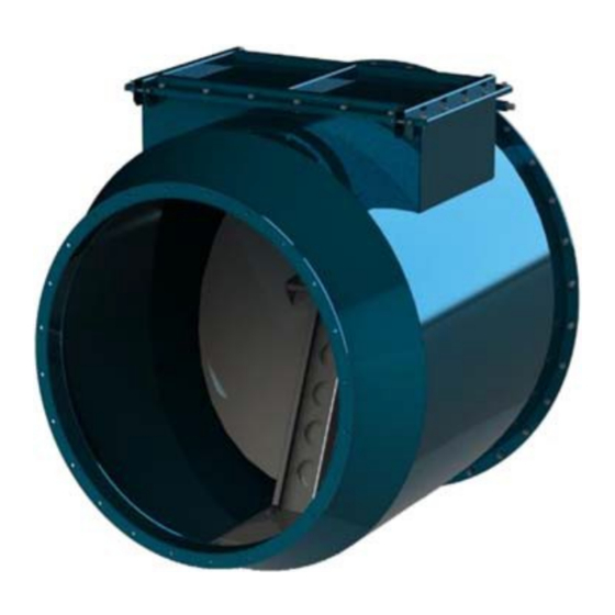
Page 4: How It Works
How it works During the normal process, the non‐return valve’s flap remains opened due to the airflow (Figure: 2). At deadlock, the valve closes due to the flap’s own weight. Figure: 2 Non‐Return Valve in open airflow configuration When an explosion takes place, the ATEX certified non‐return valve blocks the expansion of the explosion due to the front spreading pressure along the ductwork (Figure: 3). - Page 5 unblocked manually. Before unblocking the valve flap, the complete valve should be checked after an explosion has occurred for possible damage which could hinder the proper functioning. Note that the inner flap can also lock itself due to reverse current cleaning of the filter. If this is the case, the installation distance and reverse flow pressure should be checked to reduce the effect on the non‐return valve.
-
Page 6: Overall Dimensions
Overall dimensions Figure: 6 Overall dimensions Ø d Mass Type (mm) (mm) (mm) (mm) (mm) (mm) (mm) (kg) BADA000018 BADA000019 BADA000020 BADA000021 BADA000022 BADA000023 BADA000024 BADA000025 BADA000026 BADA000010 1021 +/‐ 1090 BADA000011 1035 1072 +/‐ 1120 BADA000012 1085 1127 +/‐ 1150... -
Page 7: Technical Datasheet
1.3 Technical datasheet 1.3.1 Push flow situation Considering the normal process flow direction, the situation where the fan is located upstream of the explosion source (Figure: 7). Figure: 7 Push flow situation 1.3.2 Pull flow situation Considering the normal process flow direction, the situation where the fan is located downstream of the explosion source (Figure: 8). - Page 8 individual items and to earth and the connected process structure. An earthing resistance higher than 10Ω may indicate bad earth connections; − An earth connection is provided externally on both sides and a lid of the valve. The external earth connections shall be used to bond other process parts with a equipotential bonding conductor of at least 4 mm −...
-
Page 9: Installation
2 INSTALLATION CAUTION! The non‐return valve installation, connection, start‐up and maintenance has to be performed in absence of potentially explosive atmosphere through the process interruption. CAUTION! The installation, connection, start‐up and maintenance of the non‐return valves have to be performed by qualified personnel. Use the right equipment and costumes, and do not work alone. Valve installation direction For a right installation, the air flow direction in normal working conditions has to be the same as indicated by the arrows on Figure: 9. -
Page 10: Connecting The Non-Return Valve
Connecting the non‐return valve For the best isolation effectiveness, the non‐return valve needs to be installed in proximity of the risk zone which it is wanted to be isolated. Step 1: Connect the inlet and outlet to the duct system with the correct fasteners. Step 2: Make sure that the indicator is in the correct position (Figure: 11). -
Page 11: Installation
CAUTION! Be aware of hot particles remaining inside the valve, even if the explosion is over. While opening the inspection panel, parts can fall off from the inside, damaging the operator or goods. − Every time there is a potentially explosive atmosphere danger, special safety steps must be taken, as the following: Tools or operations which can produce sparks, which can cause gas ignition, or flammable vapors, are not allowed to be used in any procedure that takes... -
Page 12: Cleaning And Checking The Inside Of The Non-Return Valve
3.1.1 Cleaning and checking the inside of the non‐return valve Step 1: Open the inspection panel as shown in Figure: 12. Figure: 12 opening inspection panel Step 2: Clean the inside of the valve and check the condition of every part. Step 3: Close the inspection as shown in Figure: 13. -
Page 13: Atex Certification
4 ATEX CERTIFICATION EXPLOSIVE ATMOSPHERE DANGER This symbol indicates information concerning the directive ATEX 2014/34/EU. Every information attended by this symbol must be executed by highly qualified personnel, competent in safety environments regarding to places characterized by the presence of potentially explosive atmospheres. -
Page 14: Dangerous Areas Classification
4.1.2 Dangerous areas classification The ATEX 2014/34/EU Directive classifies the protection system (in this case the non‐return valve) into 3 categories, with different protection levels, guaranteed to the related protection. Plant Protection Level Dust Category Very High 1D (zone 20) High 2D (zone 21) Normal... -
Page 15: Production Identification
Production identification The identification of Formula Air Group as manufacturer of the non‐return valve is due to the conformity with the current legislation by means of the following: − Declaration of conformity according to Directive ATEX 2014/34/EU − Maintenance manual −... -
Page 16: Useful Info Related To This Manual
This manual cannot be reproduced, even partially, without prior written consent by Formula Air Group. Every step of the non‐return valve all along its life cycle has been deeply analyzed by Formula Air Group in the expected area during the design, construction and manual creation. However, it is understood that nothing can replace the experience, training and good sense of those professionals who work with the device. -
Page 17: Dismantling And Recycling
6 DISMANTLING AND RECYCLING When dismantling a unit, be sure to keep in mind the following important information: CAUTION! Make sure there is no remaining any explosion potential dust of similar before dismantling. As the unit is dismantled, set aside all still functioning parts in order to re‐use them on another unit. -
Page 18: Contacts
Tel : +32 (0) 81 23 45 71 contact‐ouest@formula‐air.com customerservice@formula‐air.com www.formula‐air.com NOTE : All drawings and references contained within this manual are non-contractual and are subject to change without prior notice at the discretion of the Formula Air group and its partners.
Need help?
Do you have a question about the BADA000018 and is the answer not in the manual?
Questions and answers