Advertisement
Quick Links
Advertisement

Related Manuals for Vents A25


Summary of Contents for Vents A25
- Page 1 USER'S MANUAL Sensor control panel...
-
Page 2: Table Of Contents
This user’s manual is a main operating document intended for technical, maintenance, and operating staff. The manual contains information about the purpose, technical details, operating principle, design, and installation of the A25 unit (-s) and all of its (their) modifications. - Page 3 UNIT MOUNTING AND OPERATION SAFETY PRECAUTIONS • Do not operate the unit outside the temperature range stated in the user's • Disconnect the unit from power mains prior manual. to any installation operations. • Do not operate the unit in aggressive or explosive environments.
-
Page 4: Purpose
PURPOSE THE UNIT SHOULD NOT BE OPERATED BY CHILDREN OR PERSONS WITH REDUCED PHYSICAL, MENTAL, OR SENSORY CAPACITIES, OR THOSE WITHOUT THE APPROPRIATE TRAINING. THE UNIT MUST BE INSTALLED AND CONNECTED ONLY BY PROPERLY QUALIFIED PERSONNEL AFTER THE APPROPRIATE BRIEFING. THE CHOICE OF UNIT INSTALLATION LOCATION MUST PREVENT UNAUTHORIZED ACCESS BY UNATTENDED CHILDREN. -
Page 5: Installation, Connection To Power Mains And Set-Up
INSTALLATION, CONNECTION TO POWER MAINS AND SET-UP CUT OFF POWER SUPPLY BEFORE ANY OPERATIONS ARE PERFORMED. DO NOT LAY THE CABLE IN CLOSE PROXIMITY TO THE CONTROL PANEL CABLE! WHILE ROUTING THE CONTROL PANEL CABLE DO NOT COIL THE EXTRA LENGTH. All devices must be connected to an RS-485 network in a multidrop bus. - Page 6 CONTROL PANEL WALL SURFACE MOUNTING Route the necessary wires and cables to the control Use a screwdriver to carefully press on the latch on the unit casing end panel mounting location. face and separate the casing halves. DIP switch must be set to OFF. This rocker is to be only used by service engineers for programming the control panel. •...
- Page 7 White White Yelow Yelow Brown Brown Green Green Remove the connector with the cable from the Match the prongs of the lower part of the front panel with the slots in bracket and connect it to the female connector on the the lower part of the back panel at 45°...
-
Page 8: Network Setup
NETWORK SETUP An RS-485 network is based on a multi-master principle: • Slave devices — all the AHUs. • Master devices — all the control panels, external sensors, a smart home system etc. RS-485 network factory settings: • Controller address: 1. •... -
Page 9: Control
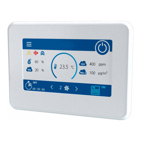
CONTROL Main page Buttons: — unit ON/OFF (Standby mode activation). — press the arrows as many times as necessary to select the desired pre-set speed. — manual speed selection mode (from the minimum permissible pre-set value to 100 %). — displayed upon pressing , adjust the speed (up/down) by pressing the arrows as many times as necessary. - Page 10 BASIC SETTINGS MENU Main page Menu Basic settings Main page Menu Basic settings Temperature 15 ˚C — set the desired temperature in the room and select from the list of air temperature control options: Ventilation — the unit only works in the heat recovery mode. Heating —...
- Page 11 Main page Menu Basic settings Schedule The weekly schedule contains four time periods for each day of the week. Once the weekly schedule is enabled in the Main page window, the air handling unit will run to a schedule using the following parameters: —...
- Page 12 Main page Menu Alarms Current alarms — number of current alarms. Indicates a serious Alarms malfunction. The unit is forced to shut down. The alarms must be reset manually. — number of current warnings. The unit is not forced Warnings to shut down.
- Page 13 ENGINEERING MENU Main page Menu Engineering menu Engineering Menu, enter the password (set to 1111 by default). To access the Engineering menu. To reset the password, set the air handling unit to the Setup mode The password can be changed via the using the Engineering menu buttons on the AHU casing (see the AHU user's manual), enter the temporary password (1111) in the...
- Page 14 Main page Menu Engineering menu Sensors Main sensor — a wired sensor connected to the control circuit board. External sensor — a remote sensor which can be contained inside the control panel or a special external device connected via RS-485, Wi-Fi, or Ethernet.
- Page 15 Main page Menu Engineering menu Main heater Select the heater type and set up its parameters. Note: if the water heater is active, prior to disabling it make sure that the heat-transfer medium supply has been disconnected and that the circuit has been drained to avoid damaging the water heater by disabling it during the cold season. Also prior to enabling either heater make sure that all the necessary sensors are physically present to avoid triggering an alarm condition and causing the AHU to shut down.
- Page 16 Main page Menu Engineering menu Cooler Select the cooler type (discrete/analogue) and its operation mode. Min. time before OFF — the minimum time for the cooler operation before deactivation. Min. time before ON — the minimum time for the cooler idling before re-activation. Cooler hysteresis —...
- Page 17 Main page Menu Engineering menu Firmware This window displays the information about the firmware installed on the AHU and the control panels. Main page Menu Engineering menu Factory settings The reset may cause a temporary loss of connection to the device as it affects the Wi-Fi, RS-485 and Ethernet settings.
-
Page 18: Alarm And Warning Codes
ALARM AND WARNING CODES Code Description Alarm! Supply fan malfunction. • Determined depending on a specific configuration. • By rpm: if the supply fan speed drops below 300 rpm for 30 seconds (configurable within a 5 to 120 second range). •... - Page 19 Warning! Heat exchanger freezing danger. Determined if the supply fan is enabled, the outdoor temperature drops below -3 ˚С and remains below -1 ˚С, and the exhaust air temperature downstream of the heat exchanger drops below 2 ˚С and remains below 3 ˚С. Warning! The battery is low.
- Page 20 V206EN-01...
Need help?
Do you have a question about the A25 and is the answer not in the manual?
Questions and answers