
Subscribe to Our Youtube Channel
Related Manuals for Schiller PRO Stand-Aer SA-30A


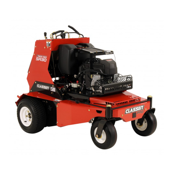
Summary of Contents for Schiller PRO Stand-Aer SA-30A
- Page 1 STAND ON AERATOR MODELS: PRO Stand-Aer® SA-30A (S/N 0448 to 506) PRO Stand-Aer® SA-30ACA (S/N 0101) OPERATOR’S MANUAL 4174369 www.classenturf.com...
-
Page 2: California Proposition
CALIFORNIA PROPOSITION 65 WARNING: Cancer and Reproductive Harm - www.P65Warnings.ca.gov. ADVERTENCIA: Cáncer y Dãno Reproductivo - www.65Warnings.ca.gov. WARNING The engine exhaust from this product contains chemicals known to the State of California to cause cancer, birth defects or other reproductive harm. ADVERTENCIA El estado de California hace saber que los gases de escape de este producto con-... -
Page 3: Important Message
You'll always be glad you did. CLASSEN ® SCHILLER GROUNDS CARE, INC. 1028 STREET ROAD, P.O. BOX 38 SOUTHAMPTON, PA 18966 PHONE 877-596-6337 • FAX 215-357-8045 TABLE OF CONTENTS .............. - Page 4 Schiller of hazard seriousness. These words appear in this Grounds Care, Inc.Engineering Department. Any manual and on the safety labels attached to Schiller Schiller Grounds Care, Inc.product that is altered, Grounds Care, Inc.machines. For your safety and...
-
Page 5: Maintenance Safety
SA-30 SAFETY MAINTENANCE SAFETY FUEL WARNING IN GENERAL – Gasoline and diesel fuels are flammable; gasoline vapors – Maintain machine according to manufacturer's are explosive. Use extra schedule and instructions for maximum safety care when handling. and best results. – Store only in containers spe- –... -
Page 6: Storage Safety
SA-30 SAFETY BATTERY JUMP STARTING WARNING Battery acid is caustic and fumes 1. Be sure the jumper cables are in good condition. are explosive and can cause seri- Turn off the ignition and all electrical accessories ous injury or death. on both machines. -
Page 7: Assembly / Set Up Instructions
SA-30 SPECIFICATIONS/ MAINTENANCE CHART ASSEMBLY / SET UP INSTRUCTIONS 1. READ THE OPERATOR'S MANUAL BEFORE ASSEMBLY. 2. Remove the brackets securing the machine to the pallet. Reinstall the caster axle nuts. Tighten the nuts. Fill tires at pressure at 15 psi on the rear tires and 25 psi on the front tires. 3. -
Page 8: Maintenance
SA-30 MAINTENANCE CHECK DAILY Operator Presence Interlock System - Start Operation For the engine to crank, the parking brake must be ON, and the operator present control lever must be re- leased in the neutral position. Stand on the operator platform and check, one by one, if the engine will crank with the parking brake OFF or the operator control lever held down. - Page 9 SA-30 MAINTENANCE TRANSAXLE & HYDRAULIC OIL Do not perform engine maintenance without the en- gine off and spark plug wires disconnected. Check cold. Add 20w50 oil if necessary to the indicated level. Do not overfill. When the oil warms up it ex- pands.
-
Page 10: Engine Oil
SA-30 MAINTENANCE ENGINE OIL Do not perform engine maintenance without the en- gine off and spark plug wires disconnected. AFTER FIRST FIVE (5) HOURS While the engine is warm: 1. Release the oil drain hose assembly from the engine clip J. Lay hose assembly over the frame edge. -
Page 11: Engine Cooling
SA-30 MAINTENANCE PURGING TRANSAXLES 2. Raise the drive wheels off the ground. Support unit with jack stands or other suitable means. Due to the effects air has on efficiency in hydrostatic 3. With the bypass valve open, and the engine drive applications, it is critical that it be purged from running, slowly move the control levers in both the system. -
Page 12: Cleaning Machine
SA-30 MAINTENANCE SPECIFIC TORQUES TINE BOLTS 15-20 FT-LBS (20-27 Nm) WHEEL LUG NUTS 75-100 FT-LBS (102-135.5 Nm) ENGINE PULLEY MOUNTING BOLT 50-60 FT-LBS (68 Nm-81Nm) WHEEL HUB NUT 120-140 FT-LBS (162.5-190 Nm) CLEANING MACHINE WASHING MACHINE Clean the machine after use. Compressed air is CAUTION: Improperly washing a machine can cause recommended. -
Page 13: Parking Brake Cable
SA-30 ADJUSTMENTS MAXIMUM AERATION DEPTH Depth stops set the maximum aeration depth. Maximum aeration depth may be adjusted by changing the hole the depth stop pin is in. Typical aeration depth is 2 1/2 - 3” (60-75 mm). Pins J1 on both sides of the machine need to be in the same hole so the tine frame is not twisted during operation. - Page 14 SA-30 ADJUSTMENTS TRACTION CONTROL LINKAGE The transaxles on this machine are spring loaded to the neutral position. The traction control levers need to be adjusted so the LH lever is in the neutral slot when the tractions are released. The right hand lever is adjusted to line up with the left hand lever.
- Page 15 SA-30 ADJUSTMENTS CHAINS Tines may drop suddenly. Support the tines when working underneath them. NOTE: It is normal for there to be some play in the chain. WHEEL AND TINE DRIVE CHAIN ADJUSTMENTS 1. Raise the machine and support it on the built in jack stands.
-
Page 16: Belt Replacement
SA-30 BELT REPLACEMENT NOTE: Use replacement belts from Schiller Grounds care, Inc. not general purpose belts. Schiller Grounds Care, Inc. belts are specifically designed for the loads of this machine and will normally pro- vide longer service life. ENGINE-TRANSAXLE BELT 1. -
Page 17: Chain Replacement
SA-30 CHAIN REPLACEMENT NOTE: It is recommended replacement chains TINE CHAIN from Schiller Grounds care, Inc. be used. Schiller Tines may drop suddenly. Support tines when work- Grounds Care, Inc. supplies a premium quality chain ing underneath them. cut to the correct length. Replace all chains together 1. - Page 18 SA-30 CHAIN REPLACEMENT WHEEL CHAIN 1. Start the engine and raise the machine ion the jack stands. See jack stands section page 19. Stop the engine. Open the transaxle by pass valves so you can rotate the tines and axles manually.
-
Page 19: Specifications
SA-30 SPECIFICATIONS SPECIFICATIONS ENGINES: DRIVE TIRES: Construction: Aluminum block with cast-in cast iron 18 X 6.50-8 sleeves. Aluminum head. Pressure: 15 p.s.i. (1.05 kg/cm²) Configuration: 4-stroke, vertical shaft, V-twin cylinder, overhead valve, air-cooled. CASTERS: 13 X 5.00-6 DRIVE SYSTEM: Pressure: 25 p.s.i. (1.75 kg/cm²) Transaxles: Dual HydroGear ZT3200 Commercial Duty Hydrostatic transaxles (10cc Pumps) AERATION:... - Page 20 SA-30 SPECIFICATIONS ENGINE MODEL NUMBER SA-30 MANUFACTURER KAWASAKI MODEL FS541V CYLINDERS COOLING FUEL Gasoline BORE/STROKE 2.9" x 2.8" (73 x 72 mm) DISPLACEMENT 36.8 ci (603 cc) COMPRESSION 8.1:1 OUTPUT POWER Refer to engine manufacturer's speci- fications and website OUTPUT TORQUE 31.0 ft-lb (42.1 Nm) @2200 rpm...
-
Page 21: Parts Section
SA-30 PARTS SECTION PARTS SECTION... - Page 22 UPPER ENGINE ASSEMBLY SA-30 FIGURE 1...
- Page 23 UPPER ENGINE ASSEMBLY SA-30 FIGURE 1 ITEM PART NO. DESCRIPTION ITEM PART NO. DESCRIPTION 4173494 S-MAIN FRAME 64018-7 BLT-CRG 3/8-16X1-1/4 64018-44 BLT-CRG 3/8-16X1 SN 64001-6 NUT-HEX JAM 3/8-16 4171512.7 PLT-ENGINE MOUNTING 64263-007 BLT-FLG HD M8-1.25 X 20 64262-002 BLT-FLG HD 1/4-20 X 3/4 64268-03 NUT-FL NYLON LOCK 3/8-16 4172292.7...
- Page 24 LOWER ENGINE ASSEMBLY SA-30 FIGURE 2...
- Page 25 LOWER ENGINE ASSEMBLY SA-30 FIGURE 2 ITEM PART NO. DESCRIPTION ITEM PART NO. DESCRIPTION 4171512.7 PLT-ENGINE MOUNTING 4173822 PUMP-GEAR 2.1XCC 4171447 PULLEY-4 IN 4164382 ENGINE-KAW FS541V ES 2690030-03 FTG-3/4-16 ORB X 1/2 BARB 4173494 S-MAIN FRAME 64006-06 LOCKWSHR-7/16 HELICAL 2308000 PULLEY-IDLER 4.00 EOD 25-2503-8-6 FITTING 90 -8 MORB X -6 MJIC...
- Page 26 FUEL TANK, BATTERY, RESERVOIR SA-30 FIGURE 3 USED ON 554930 ONLY SA-30 (10”) To Carburetor (36”) (7”) USED ON (12”) SA-30CA 554930CA ONLY 32 31 (41.5”) (21.5”) Carburetor To Rollover Vent on Tank...
- Page 27 FUEL TANK, BATTERY, RESERVOIR SA-30 FIGURE 3 ITEM PART NO. DESCRIPTION ITEM PART NO. DESCRIPTION 4173494 S-MAIN FRAME 4174266-1 TANK-FUEL, MIDSIZE (INCLUDES ITEMS 3-7) 4174343 GROMMET, ROLL-OVER 4165763 TANK VENT 4132325 GROMMET-SEALING 4165561-2 TUBE-FUEL, PICK-UP 4165291 CAP-FUEL, 3.5IN EPA 4162977-001 HOSE-FUEL 1/4 INCH 88042N CLAMP-HOSE 4165864...
-
Page 28: Wheel Assemblies
WHEEL ASSEMBLIES SA-30 FIGURE 4... - Page 29 WHEEL ASSEMBLIES SA-30 FIGURE 4 ITEM PART NO. DESCRIPTION ITEM PART NO. DESCRIPTION 4172857 ASSY-WHEEL 13X5.00-6 64018-7 BLT-CRG 3/8-16X1-1/4 64187-03 NUT-WHEEL 1/2-20 4171862 ASSY-WHEEL 18X6.50-8 64123-215 BLT-HEX 3/4-10X7-1/2 64229-07 NUT-NYLON LOCK 3/4-10 2722231 SPACER-END 2722230-02 SPANNER 4173176 WLDMT-AXLE SHAFT 64268-03 NUT-FL NYLON LOCK 3/8-16 4171458.7 WLDMT-WHEEL SPINDLE HOUS 2...
-
Page 30: Parking Brake Assy
PARKING BRAKE ASSY SA-30 FIGURE 5... - Page 31 PARKING BRAKE ASSY SA-30 FIGURE 5 ITEM PART NO. DESCRIPTION ITEM PART NO. DESCRIPTION 4171573.7 BRKT-BRAKE MOUNT 4174464 S-BRAKE ARM BRAKT (INCLUDES ITEM 10) 4176120 KNOB-THREADED 4176129 WLDMT-BRAKE HANDLE 4173527.7 BRKT-BRAKE, PARKING 4173896.7 BRKT-CABLE 4117212 SPRING-EXTENSION 4173898 CABLE-BRAKE, PARKING 4174337 HUB-BRAKE PIVOT 10 4166324-04 BEARING-PLASTIC 1.000 ID...
-
Page 32: Electrical System
ELECTRICAL SYSTEM SA-30 FIGURE 6 ENGINE KILL CHARGE CONNECTION (RED) CARB SOLENOID TO STARTER BATTERY TO SOLENOID (2) (BLACK) BATTERY GROUND ENGINE BLOCK (GROUND) (RED) SOLENOID SOLENOID STARTER SOLENOID CHARGING RELAY AUXILIARY POWER HOUR METER PARK BRAKE SWITCH LIFT SWITCH WIRE COLORS AND GAUGE CODE COLOR... - Page 33 ELECTRICAL SYSTEM SA-30 FIGURE 6 ITEM PART NO. DESCRIPTION ITEM PART NO. DESCRIPTION 4172161 HARNESS-WIRING MAIN (INCLUDES ITEM 9) 128010 KEY-SWITCH 2722325 RELAY-40AMP SEALED 38665 SOLENOID 108208 SWITCH-DBL POLE 4171992 METER-HOUR 2308094 SWITCH NCNC 4171893 SWITCH-ROCKER 148082-20 FUSE-20 AMP 10 4171099 BATTERY-AGM TYPE 4171973 CHARGER-AGM...
-
Page 34: Transaxle Assembly
TRANSAXLE ASSEMBLY SA-30 FIGURE 7 FROM RESERVIOR TO OIL COOLER... - Page 35 TRANSAXLE ASSEMBLY SA-30 FIGURE 7 ITEM PART NO. DESCRIPTION ITEM PART NO. DESCRIPTION 4171283 TRANSAXLE, HYDROSTATIC RH 1 4142045-06 FILTER-TRANSAXLE 4171282 TRANSAXLE, HYDROSTATIC LH 4172890.7 BRKT-SHIELD SUPPORT 4148697 ROD-PULL FREEWHEEL 64268-02 NUT-FL NYLON LOCK 5/16-18 4173645 SPACER-BUSHING 4169194 BUSHING - .522 X ..688 X .289 64163-29 WSHR-21/64 X 1 X 11GA 4174382...
-
Page 36: Oil Cooling System
OIL COOLING SYSTEM SA-30 FIGURE 8 6.5” (7.75”) 10 9 29”) (33”) (17.5”) (11.25”) (2.63’) (3.25”) (5.75”) (20”) (20”) (9.625”) - Page 37 OIL COOLING SYSTEM SA-30 FIGURE 8 ITEM PART NO. DESCRIPTION ITEM PART NO. DESCRIPTION 2188173 COOLER-OIL 4174463 S-RESERVOIR 4171280 MANIFOLD-AERATOR 4171284 GAUGE-HYDRAULIC 0-1000 PSI 1 4171281 CYLINDER-2.25 X 3.0 4173822 PUMP-GEAR 2.11CC 4171282 TRANSAXLE, HYDROSTATIC LH 1 4171283 TRANSAXLE, HYDROSTATIC RH 1 4142045-06 FILTER-TRANSAXLE 2720396...
- Page 38 CONTROL PANEL & TOWER ASSY SA-30 FIGURE 9 RESERVOIR TANK CYLINDER TO PUMP...
- Page 39 CONTROL PANEL & TOWER ASSY SA-30 FIGURE 9 ITEM PART NO. DESCRIPTION ITEM PART NO. DESCRIPTION 4173504 S-CONTROL PANEL INCLUDES ITEM 2 4176220 LABEL-CONTROL PANEL 4171992 HOUR METER-MAG SENSE 128010 SWITCH KEY 64141-2 NUT-WLF 1/4-20 4172326-01 HOSE-#4JIC/JIC 90 LG 17.38 4171284 GAUGE-HYDRAULIC 0-1000 PSI 1 118020-22...
-
Page 40: Handle Controls
HANDLE CONTROLS SA-30 FIGURE 10... - Page 41 HANDLE CONTROLS SA-30 FIGURE 10 ITEM PART NO. DESCRIPTION ITEM PART NO. DESCRIPTION 64018-44 BLT-CRG 3/8-16X1 SN 64262-012 BLT-FLG HD 3/8-16 X 1-1/4 64268-01 NUT-FL NYLON LOCK 1/4-20 64140-18 COTTER PIN-1/4-2 64262-013 BLT-FLG HD 3/8-16 X 1-1/2 64018-51 BLT-CRG 5/16-18 X 3/4 SN 64229-03 NUT-NYLON LOCK, 3/8-16 4171478.7...
- Page 42 DEPTH STOP & HOC ASSEMBLY SA-30 FIGURE 11...
- Page 43 SA-30 DEPTH STOP & HOC ASSEMBLY FIGURE 11 ITEM PART NO. DESCRIPTION ITEM PART NO. DESCRIPTION 4117212 SPRING-EXTENSION 4176366.7 PLATE-GUIDE 4176416.7 PLATE-RATCHET 2183071-04 SPACER 4169597 EYE BOLT 5/16-18 X 1.5 83-5013E08 SPROCKET-WHEEL,FRONT 4172671 ARM-DEPTH 4172672 HUB-DEPTH ARM 4174327.7 WLDMT-DEPTH SET RH 4174326.7 WLDMT-DEPTH SET LH 4176365.7...
-
Page 44: Jackshaft Assembly
JACKSHAFT ASSEMBLY SA-30 FIGURE 12... - Page 45 JACKSHAFT ASEMBLY SA-30 FIGURE 12 ITEM PART NO. DESCRIPTION ITEM PART NO. DESCRIPTION 4174137 SPACER 64141-6 NUT-WLF 5/16-18 64018-15 BLT-CRG 5/16-18X1 SN 64123-24 BLT-HEX 1/2-13X2 64284-16 NUT-FL CRLK 5/8-18 64141-13 NUT-WLF 1/2-13 4171394.7 WLDMT-TINE ASSY 64044-18 SCREW-SET 5/16-18 x 5/16 64164-28 KEY-1/4 X 1 #15 WOODRUFF 64221-1...
-
Page 46: Tine Assembly
TINE ASSEMBLY SA-30 FIGURE 13... - Page 47 TINE ASSEMBLY SA-30 FIGURE 13 ITEM PART NO. DESCRIPTION ITEM PART NO. DESCRIPTION 4171394.7 WLDMT-TINE ASSY 4171322.7 WLDMT-TINE BANK RH 64141-6 NUT-WLF 5/16-18 64018-15 BLT-CRG 5/16-18X1 SN 4172865 LINK-CONNECTOR 4172864-02 CHAIN-50 ROLLER 63 PITCH 4173503 KIT-CHAIN (INCLUDES ALL 6 CHAINS FOR UNIT AND LINKS) 64044-13 SCREW-SET 1/4-28X1/4 64044-18...
- Page 48 PLATFORM, PAD & JACKSTANDS SA-30 FIGURE 14...
- Page 49 PLATFORM, PAD & JACKSTANDS SA-30 FIGURE 14 ITEM PART NO. DESCRIPTION ITEM PART NO. DESCRIPTION 4172224.17 PLT-JACK 4172688 PIN-JACK 4173046 BUSHING-LATCH ARM 64268-02 NUT-FL NYLON LOCK 5/16-18 64018-58 BLT-CRG 5/16-18X1-3/4 64163-108 WSHR-.334 X 1.25 X .125 4171391 BUSHING-SPACER 64262-027 BLT-FLG HD 3/8-16 X 2-1/4 GR8 2 64268-03 NUT-FL NYLON LOCK 3/8-16 64141-13...
- Page 50 COVERS & GUARDS SA-30 FIGURE 15...
- Page 51 SA-30 FIGURE 15 ITEM PART NO. DESCRIPTION ITEM PART NO. DESCRIPTION 4172177.17 COVER-WEIGHT 4171538.17 PLT-WEIGHT 4172194.17 WLDMT-HITCH 4172869 PLUG-HITCH TUBE 4172703.7 PLT-WEIGHT,CENTER 4172853.17 WLDMT-COVER FRONT 64141-6 NUT-WLF 5/16-18 2183071-03 SPACER-15.88X10.32X24 64018-51 BLT-CRG 5/16-18 X 3/4 SN 4171535.17 COVER-TOP FRONT 4171537.17 COVER-FRONT, RH 4171536.17 COVER-FRONT, LH...
-
Page 52: Under Cover
DECALS SA-30 FIGURE 16 6 & 7 15 & 3 UNDER COVER... - Page 53 DECALS SA-30 FIGURE 16 ITEM PART NO. DESCRIPTION ITEM PART NO. DESCRIPTION 4176220 LABEL- CONTROL PANEL 2000570 LABEL-WARN FUEL PICT. 2000577 LABEL WARNING 2000590 LABEL WARN BATTERY 4172910 LABEL-RESERVOIR 4171963 LABELCLASSEN BLACK 4171825 LABEL-PRO 4172912 LABEL-HYDRA-COOL 4172915 LABEL-JACKSTAND 4172911 LABEL-SLOPES, CA SPARK 4172914 LABEL-TINES 4172886...
- Page 54 All claims must be received by the factory 30 days after the end of the warranty period to receive warranty consideration. CLASSEN ® SCHILLER GROUNDS CARE, INC. 1028 STREET ROAD, P.O. BOX 38 SOUTHAMPTON, PA 18966 PHONE 877-596-6337 • FAX 215-357-8045 ©2016 Schiller Grounds Care, Inc. All Rights Reserved.
Need help?
Do you have a question about the PRO Stand-Aer SA-30A and is the answer not in the manual?
Questions and answers