Table of Contents
Advertisement
Quick Links
Проконсультироваться и купить данное оборудование вы можете в компании «АНД-Системс»
адрес: 125480, г.Москва, ул.Туристская, д.33/1; site: https://andpro.ru тел: +7 (495) 545-4870 email: info@andpro.ru
При обращении используйте промокод AND-PDF и получите скидку.
Liebert
®
User Manual
Infrastructure Management & Monitoring
For Business-Critical Continuity™
IntelliSlot
®
Relay Card
Advertisement
Table of Contents

Related Manuals for Emerson Liebert IntelliSlot IS-RELAY


Summary of Contents for Emerson Liebert IntelliSlot IS-RELAY
- Page 1 Проконсультироваться и купить данное оборудование вы можете в компании «АНД-Системс» адрес: 125480, г.Москва, ул.Туристская, д.33/1; site: https://andpro.ru тел: +7 (495) 545-4870 email: info@andpro.ru При обращении используйте промокод AND-PDF и получите скидку. Infrastructure Management & Monitoring For Business-Critical Continuity™ Liebert IntelliSlot Relay Card ®...
-
Page 2: Table Of Contents
TABLE OF CONTENTS ....... 1 NTRODUCTION Inspecting Shipment on Receipt ......1 . -
Page 3: Introduction
Upon accepting shipment, inspect the packaging and product for any damaged or missing parts. If any damage is observed, report it to the shipping company and your local Emerson Network Power representative. If any components are missing, contact your local representative for replacement. -
Page 4: Installation
Installation NSTALLATION Make sure you have the following parts and tools before you begin. Required Parts and Tools • Liebert IntelliSlot Relay Card (provided) • #2 (medium) Phillips or small flathead screwdriver Instructions 1. Turning off the unit prior to installation is suggested, although not required. -
Page 5: Jumper Setup
Installation 6. Use these guidelines for terminal block specifications: Acceptable Wire Size Wire Strip Length 24-16 AWG 0.24-0.28 in. (6-7mm) Proceed to the following sections: • 3.0 - Pin Configuration to configure the terminal blocks. • 4.0 - Jumper Setup to configure the jumpers. -
Page 6: Pin Configuration
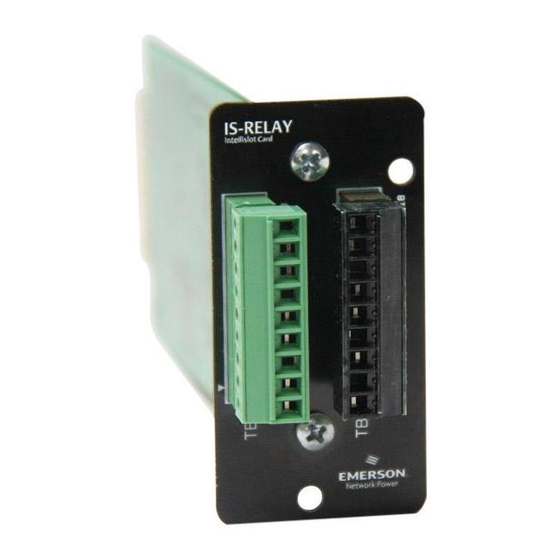
Pin Configuration ONFIGURATION The card has two terminals blocks, TB1 (green, numbered 1-9) and TB2 (black, 10-18), as shown in Figure 1. Figure 1 Pin location and numbering green black Refer to your Liebert product user manual for the pin configuration for the terminal blocks. -
Page 7: Figure 2
Jumper Setup UMPER ETUP The card has five jumpers, P3 through P7, as shown in Figure 2. Each jumper connects two pins. Figure 2 Jumper location and numbering FRONT OF Jumper CARD Jumper Jumper Jumper Jumper By default all five jumpers have shunts installed. The two pins are shunted together to provide the functions shown in Table 2, allowing relay commons to be tied together. - Page 8 Embedded Power Services Infrastructure Management & Monitoring Surge Protection Emerson, Business-Critical Continuity, Emerson Network Power and the Emerson Network Power logo are trademarks and service marks of Emerson Electric Co. or one of its affiliated companies. ©2010 Emerson Electric Co.
Need help?
Do you have a question about the Liebert IntelliSlot IS-RELAY and is the answer not in the manual?
Questions and answers