Alesis 3 User Manual
Digital reverb
Hide thumbs
Also See for 3:
- Quick start manual (17 pages) ,
- Reference manual (63 pages) ,
- Instruction manual (6 pages)
Advertisement
Table of Contents
Advertisement
Table of Contents

Related Manuals for Alesis 3


Summary of Contents for Alesis 3
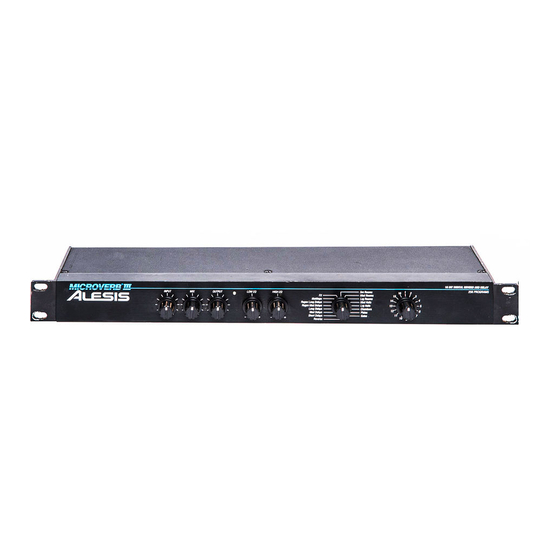
- Page 1 Alesis MICROVERB III Users Manual...
- Page 2 The entire digital processing system is contained on a single chip, developed by the Alesis design team specifically for the MICROVERB III. Using high speed complementary-metal-oxide-semiconductor (CMOS) silicon processing, the MICROVERB III chip replaces several circuit cards of components while providing a powerful level of sonic flexibility that will expand and polish the sound of any recording.
- Page 3 DEFEAT JACK at the outputs. Any SPST type footswitch (such as the reverb footswitch that sometimes comes with amplifiers) will work for this function. is actually a 3 colored LED that shows several input conditions. When control should be decreased. INPUT reads in the red only on occasional transients.
-
Page 4: Installation
INSTALLATION Before unpacking your new Alesis MICROVERB III unit, take a moment to look through this instruction manual. We’ve made it brief and informative and it will answer any questions that you might have. Some helpful setup thoughts are included along with some useful application hints. -
Page 5: Power
Another way of interfacing the MICROVERB III unit to a mixer or recording console would be in-line across the output of your mixing console. See figure 3 This method should only be used if you needed to effect the entire mix, since the same effect would be on all of the instruments or vocals. -
Page 6: Operation
INPUT program peaks. The LED should remain “green” most of the time. This indicates that there is sufficient level to maintain a good signal to noise ratio. 3. Increase the OUTPUT 4. Adjust the control until the desired ratio of dry to wet signal is achieved. - Page 7 APPLICATIONS About Reverb... Reverb can be thought of as a great number of distinct echoes (called reflections) that occur so fast and in such large number that our ear hears them and interprets them as one sound - the distinct sound we know as reverb.
-
Page 8: Multitap Delay
GATES Gated reverb is a very popular effect on drums first found on English records in the early 1980’s. The MICROVERB III’s gate programs simulate applying a noise gate (a device that automatically decreases or cuts off the volume once a signal falls below a certain level) across the output of the reverb causing the initial attack of the reverb to sound very big, but the tail of the reverb to be cut off very quickly. -
Page 9: Specifications
SPECIFICATIONS ELECTRICAL CHARACTERISTICS FREQUENCY RESPONSE DYNAMIC RANGE HARMONIC DISTORTION INPUT NUMBER OF CHANNELS NOMINAL LEVEL MAXIMUM LEVEL IMPEDANCE A/D - D/A CONVERSIONS CONVERSION SCHEME PROCESSOR SPEED PROCESSOR MEMORY SAMPLING FREQUENCY OUTPUT NUMBER OF CHANNELS FORMAT MAXIMUM LEVEL IMPEDANCE FRONT PANEL CONTROLS Input Level Mix Level...
Need help?
Do you have a question about the 3 and is the answer not in the manual?
Questions and answers