
Related Manuals for KEB C6 HMI


Summary of Contents for KEB C6 HMI
- Page 1 COMBICONTROL C6 HMI / C6 HMI LC Instruction Manual Document Part Version 20125246...
-
Page 3: Table Of Contents
Rear view ......................................15 Side view ......................................17 Connection overview C6 HMI 4.3” ..............................19 2.8.1 Labels......................................19 Connection overview C6 HMI / C6 HMI LC 5.7” and higher ........................ 20 2.9.1 Connection Label ..................................20 2.9.2 Nameplate ....................................21 2.10... - Page 4 Starting the project ..................................53 5.1.8 Debugging the project ................................. 54 5.1.9 Transfer the project from C6 HMI / C6 HMI LC to the configuration PC ..................56 5.1.10 Backup and restore ................................. 57 5.1.11 Update the operating system ..............................57 COMBIVIS studio 6 project ................................
-
Page 5: Introductory Information
SECTION Introductory Information... -
Page 6: General Notes
The information in this manual is subject to change and is in no way binding upon KEB. b) KEB is not responsible for technical errors or other omissions in the manual, and shall not accept any responsibility deriving from its use. -
Page 7: Description Of Safety Symbols
Das Symbol auf dem Produkt oder seiner Verpackung weist darauf hin, dass dieses Produkt nicht als normaler Haushaltsabfall zu behandeln ist, sondern an einem Sammelpunkt für das Recycling von elektrischen und elektronischen Geräten abgegeben werden muss. Durch ihren Beitrag zum korrekten Entsorgen dieses Produkts schützen Sie die Umwelt und die Ge- sundheit Ihrer Mitmenschen. -
Page 8: Qualified Personnel
COMBIVIS connect. 1.9 The manual is a part of the system This user’s guide belongs to C6 HMI / C6 HMI LC and is also required for commissioning. b) Keep all supplied documentation for the entire service life of C6 HMI / C6 HMI LC. -
Page 9: Scope Of The Operating Instructions
The cabinet in which C6 HMI / C6 HMI LC is installed may on- ly be accessed with a key or tool and only by trained and authorized person- nel. -
Page 10: Description
SECTION Description... -
Page 11: Product Description
The C6 HMI family is the HMI solution with RISC architecture that allows running COMBIVIS studio HMI and COMBIVIS connect software platforms. The C6 HMI LC family is the HMI & Control solution that integrates the COMBIVIS studio HMI visualization software and the CONTROL Basic Runtime integrating in one single product both the visualization and the process control part. -
Page 12: Configuration
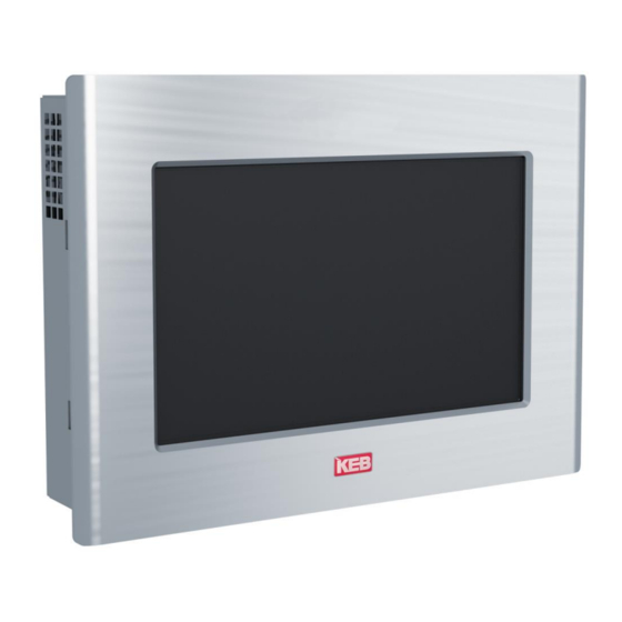
2.4 Configuration The following figures show the various configurations. 2.4.1 C6 HMI/C6 HMI LC (full aluminium front panel) Figure 1 C6 HMI / C6 HMI LC 5.7” 4.3” 5.7” 7.0“W 8.4” 10.1”W C6 HMI Full aluminium front panel 10.4” 12.1”... -
Page 13: Front View
2.5 Front view 2.5.1 Full aluminium front panel Figure 2 Full aluminium front panel detail Full aluminium front panel Touchscreen-Display... -
Page 14: Widescreen
2.5.2 Widescreen In the C6 HMI / C6 HMI LC family the systems with 5.7", 8.4", 10.4", 12.1", 15.0" dis- play have a 4:3 aspect ratio, whereas the systems with 4.3", 7.0”W, 10.1”W, 12.1”W and 15.6"W display have a aspect ratio of 15:9 or 16:9. -
Page 15: Rear View
2.6 Rear view Figure 4 C6 HMI 4.3” rear view Ventilation holes Mounting seal Figure 5 C6 HMI / C6 HMI LC 5.7” rear view Ventilation holes Note: rear panels may be different de- pending on display size. Mounting seal Figure 6 C6 HMI / C6 HMI LC 7.0”... - Page 16 Figure 7 C6 HMI / C6 HMI LC 8.4” rear view Aeration holes Mounting seal...
-
Page 17: Side View
2.7 Side view Figure 8 C6 HMI 4.3” side view Aeration holes Figure 9 C6 HMI 4.3” side view Aeration holes Recess for fixing clamps... - Page 18 Figure 10 C6 HMI / C6 HMI LC 5.7” side view Aeration holes Recess for fixing clamps Figure 11 C6 HMI / C6 HMI LC 5.7” side view Aeration holes Recess for fixing clamps...
-
Page 19: Connection Overview C6 Hmi 4.3
Power on LED COM 1 (RS232/422/485/MPI) USB1 (2.0) LAN1 (100 Mbit/s) Buzzer Reset button COM RX LED 2.8.1 Labels On the rear panel are present the following the connectors label. Figure 13 C6 HMI / C6 HMI LC connectors label detail... -
Page 20: Connection Overview C6 Hmi / C6 Hmi Lc 5.7" And Higher
2.9 Connection overview C6 HMI / C6 HMI LC 5.7” and higher Figure 14 C6 HMI / C6 HMI LC 5.7” connectors Power DC input LAN1 (100 Mbit/s) Fieldbus USB2 (2.0) LAN2 (10/100 Mbit/s) CV connect Reset button Power on LED SD card slot USB1 (2.0) -
Page 21: Nameplate
2.9.2 Nameplate Figure 16 C6 HMI / C6 HMI LC label detail Model UL marking CE marking Material number Serial number 2.10 Touchscreen Size Touchscreen Panel technology Table 2 4.3” Touchscreen 4 - wire 5.7” 7.0“W The touchscreen is installed from the back of the 8.4”... -
Page 22: Putting In Operation C6 Hmi / C6 Hmi Lc
2.11 Putting in operation C6 HMI / C6 HMI LC To put in operation C6 HMI / C6 HMI LC the followings two phases must be done: ● Configuration and creation of the project of C6 HMI / C6 HMI LC. -
Page 23: Software Options
2.12 Software options COMBIVIS studio HMI COMBIVIS studio HMI Function BASIC for Win CE ADVANCED for Win CE RealTime DB Max. 512 bytes Max. 4096 bytes Table 3 Scaling Software options ODBC Realtime Trace DB Data Structure OPC Client DA Network Graphic Interface Vectorial Graphic Editor... - Page 24 Table 9 Dynamic Multilanguage Dynamic multilanguage Unicode support Table 10 Drivers Drivers Max. number of Driver PLC Tag Importer Table 11 Event Object Event Object Table 12 Scaling Object Scaling Object Table 13 Scheduler Object Scheduler Object Logics Table 14 IL Logic (Step5-Step7) Logics VBA Logic (WinWrap Basic)
-
Page 25: Installation And Connection
SECTION Installation and connection... -
Page 26: Preparation For Installation
Ensure that the ventilation holes are not covered. 3.1.2 Portrait Mounting C6 HMI / C6 HMI LC can be mounted in portrait mode; the display can be ro- tated according to the mounting position using the dedicated utility from the panel control panel. ... -
Page 27: Mounting Position
An inclined installation reduces the thermal convection by the HMI device and the maximum permissible ambient temperature for operation. Please contact KEB for details. The HMI device may otherwise be damaged and its certifications and war- ranty will be void. -
Page 28: Checking Installation Distances
3.5 Checking installation distances To ensure adequate ventilation it is necessary leaving the following open spaces around the system: X direction: (min.) 15 mm for each side. Y direction: (min.) 50 mm for each side. Z direction: (min.) 10 mm. Figure 20 Installation distances 3.6 Preparing the mounting cut-out... -
Page 29: Degrees Of Protection
Deviations of the plane of the mounting cut-out limits: ≤ 0.5 mm. This condition must also be met with installed C6 HMI / C6 HMI LC. Allowed surface roughness in the area of the seal: ≤ 120 microns (Rz 120). -
Page 30: Mounting The Device
HMI / C6 HMI LC size. System Clamp Quantity Clamp position C6 HMI / 4.3” C6 HMI / C6 HMI LC / 5.7” C6 HMI / C6 HMI LC / 7.0”W C6 HMI / C6 HMI LC / 8.4” C6 HMI / C6 HMI LC /... -
Page 31: Tools To Tighten The Mounting Clamps
C6 HMI / C6 HMI LC / 10.4” C6 HMI / C6 HMI LC / 12.1” C6 HMI / C6 HMI LC / 12.1”W C6 HMI / C6 HMI LC / 15.0” C6 HMI / C6 HMI LC / 15.6”W 3.7.2... -
Page 32: Procedure
3.7.3 Procedure Insert C6 HMI / C6 HMI LC into the mounting cut-out from the front. Figure 21 Installation Figure 22 Installation... - Page 33 Figure 23 Installation Insert the fixing clamps into the housings of the device. Figure 24 Installation Figure 25 Installation...
- Page 34 Tighten the fixing clamps with a 1.5 mm hex key. Figure 26 Installation Note: adhere to the permissible torque when tightening the threaded pin of the mounting clamp: 0.2 Nm. Figure 27 Installation Repeat steps 2 and 3 for all mounting clamps. Check the seal seat.
-
Page 35: Connecting The Unit
3.8 Connecting the unit 3.8.1 Information for the connection The C6 HMI / C6 HMI LC must be installed in accordance with the data contained in this instruction manual. This units are designed for the connection with a "Secondary Circuit Overvoltage Category II". -
Page 36: Switching On And Testing The Device
Figure 29 Power supply connection detail 3.8.3 Switching on and testing the device Connect the power supply cable to C6 HMI / C6 HMI LC. Switch On the power supply. The green led will light. Figure 30 Power supply connection detail The display will switch on accordingly, and after few seconds the Windows CE desktop will appear. -
Page 37: Connecting The Configuration Pc
IP address to the C6 HMI / C6 HMI LC. If no DHCP server is available, assign a static IP address to the C6 HMI / C6 HMI LC which is compatible with the IP address of the configuration computer. - Page 38 Figure 32 Connecting the configuration PC Click on Ok to save the settings Click on Start -> Settings -> Control Panel Figure 33 Connecting the configuration PC...
- Page 39 Then double click on “Registry Saver” Figure 34 Connecting the configuration PC Click on the “Save” button and confirm clicking on “Ok”. This operation will save your setting in a permanent way. Figure 35 Connecting the configuration PC...
-
Page 40: Procedure
3.9.1 Procedure After the connection between C6 HMI / C6 HMI LC and the configuration PC, to trans- fer the project into C6 HMI / C6 HMI LC you must: Start COMBIVIS studio HMI Developing tool. Load the project to transfer. - Page 41 USB Key Hard Disk USB key inserted into a USB port of C6 HMI / C6 HMI LC. In the picture below an example of file Explorer on C6 HMI / C6 HMI LC. Figure 38 Connecting the configuration PC...
-
Page 43: Commissioning The Device
SECTION Commissioning the device... -
Page 44: Backup Design
After the operation you can make the NAND memory “read only” as before. In order to set the NAND memory to "read only", click in the C6 HMI / C6 HMI LC Windows folder on MakeNANDReadOnly (see picture below). -
Page 45: Slot For Memory Card (From 5.7")
4.3 Slot for memory card (from 5.7") C6 HMI / C6 HMI LC can optionally accommodate an SD/SDHC card slot V. 2.0 (push- push type). Figure 40 Slot for memory card Slot for memory card memory card (example) 4.4 Installation/removal of a memory card... - Page 46 Figure 43 Slot for memory card Push the card previously inserted. Figure 44 Slot for memory card Extract the memory card from the slot. Figure 45 Slot for memory card...
-
Page 48: Commissioning A Project
SECTION Commissioning a project... -
Page 49: Combivis Studio Hmi Project
RS 232 RS 422 RS 485 C6 HMI / C6 HMI LC comes as default with the serial port set as RS 232. If you want to change the type of serial communication you must do the following:... - Page 50 Click on Start -> Settings -> Control Panel Figure 46 Configuring the serial port Double click on “Serial Port Configuration” Figure 47 Configuring the serial port Choose the type of serial communication Figure 48 Configuring the serial port...
-
Page 51: Connecting The Serial Port
5.1.5 Project administration The C6 HMI / C6 HMI LC has high-performance tools to manage a running project. With the same mask that is used for the project transfer (see below), you can also: stop the C6 HMI / C6 HMI LC project from the configuration PC... -
Page 52: Stopping The Running Project
Select TCP in the upper left list Insert the IP address of the C6 HMI / C6 HMI LC Click the button “Stop Device Project!” You will see the project in C6 HMI / C6 HMI LC stopping (see below) Picture 51 Stop running project... -
Page 53: Starting The Project
Picture 52 Starting the project To start a project in C6 HMI / C6 HMI LC by using the configuration PC you must: Select TCP in the upper left list Insert the IP address of the C6 HMI / C6 HMI LC 10. -
Page 54: Debugging The Project
Transfer the project to the C6 HMI / C6 HMI LC and start running. NOTE: Ensure that the project is running; otherwise you cannot debug it. In order to debug the running project of the C6 HMI / C6 HMI LC from the configura- tion PC, follow these steps:... - Page 55 Debugging the project The following window will appear: Picture 55 Debugging the project Enter the IP address of the C6 HMI / C6 HMI LC and click "OK". A new window opens that asks for the user and the password...
-
Page 56: Transfer The Project From C6 Hmi / C6 Hmi Lc To The Configuration Pc
Transfer the project from C6 HMI / C6 HMI LC to the configuration PC This option allows you to transfer the project from C6 HMI / C6 HMI LC to the con- figuration PC in order to check or to change and hence transfer again into C6 HMI / C6 HMI LC. -
Page 57: Backup And Restore
5.1.10 Backup and restore The C6 HMI / C6 HMI LC has tools to backup and restore the contents of its internal memory in order to manage the project and the operating system of C6 HMI / C6 HMI LC. -
Page 58: Combivis Studio 6 Project
5.2 COMBIVIS studio 6 project This chapter is valid only for C6 HMI LC systems which are coming with CONTROL Runtime pre-installed directly from production. 5.2.1 C6 HMI LC – Implementation “CONTROL Runtime” The CONTROL Runtime runs as a thread with “real time” priority. -
Page 59: Preparing The Combivis Studio 6 Programming Environment
The COMBIVIS studio 6 programming environment must be properly configured in order to support the code compiler for C6 HMI LC systems. You need COMBIVIS studio 6 version 6.2.1.0_3.5.3.50 or above installed on the PC. COMBIVIS studio 6 installation can be found in the COMBIVIS studio 6 user manual. - Page 60 Create now a new project and insert the C6 HMI LC as new Device as shown in the following figure.
-
Page 61: Transferring The Combivis Studio 6 Application To The Target System
Modbus TCP on LAN1 Modbus RTU To insert the I/O master right click on the C6 HMI LC device icon on the project tree, select “Add Device” and select from the “Vendor” list box. The list will be populated with the available master devices. Select the one required by your application in be-... -
Page 62: Support For Retentive Data
All running IEC tasks are terminated so the retentive areas are consistent The system starts flushing the retentive memory areas to a file which is saved on disk The CONTROL Runtime is terminated The panel continues to run until the Micro UPS is able to provide power to C6 HMI... - Page 63 64KB for the PERSISTENT memory type. Note: If the power supply returns before the energy inside the Micro UPS is fin- ished, and actually C6 HMI LC has not been switched off, the following operations are carried on: - The display is switched on...
-
Page 64: Use In Combination With Combivis Hmi Runtime
COMBIVIS HMI Runtime can be of course configured to communicate with the CON- TROL Runtime. The C6 HMI LC includes the Gateway which is then used as communication inter- face. The COMBIVIS studio HMI project must be configured to communicate with a gener- ic CODESYS controller inserting in the “Real Time DB”... -
Page 65: Use In Combination With Combivis Connect
The CONTROL Runtime running on a C6 HMI LC device can be reached also from a panel which has been configured to belong to the same sub network. When having on the same sub network more than one C6 HMI LC system, you need to assign to them different name. -
Page 66: Limitations And Recommendations
5.2.8 Limitations and Recommendations In order to get the best balancing between functionalities and performances we strongly suggest to follow some guidelines when designing the applications for COMBIVIS studio 6 and COMBIVIS studio HMI. The PLC cycle time must be greater or equal than 10ms; the average jitter has been measured around +/- 2ms In general the CPU time reserved to CONTROL Runtime shall not be greater than 25%;... -
Page 67: Maintenance
SECTION Maintenance... -
Page 68: Calibration Of The Touchscreen
6.1 Calibration of the Touchscreen C6 HMI / C6 HMI LC is designed to don’t require touchscreen calibration, but in some cases, like update of the operating system, you must recalibrate the touch screen. To calibrate the touch screen: ... -
Page 69: Maintaining & Cleaning
Click on the “Recalibrate” button and follow the instructions. 6.2 Maintaining & cleaning C6 HMI / C6 HMI LC is designed for maintenance-free operation except for the re- placing of the battery backup when necessary. It is recommended to clean the touchscreen with a damp cleaning cloth and a display cleaning solution. -
Page 70: Procedure
6.2.1 Procedure Proceed as follows: Switch off the HMI device or lock the touch screen. b) Spray the cleaning solution onto a cleaning cloth. Do not spray directly onto the display. d) Clean the display from the screen edge inwards. 6.2.2 Backup battery replacement (CR2032 3V) ... - Page 71 The following figures relate to the display models from 8.4“ (inches). Remove the two screws as indicated in figure. Figure 63 Backup battery replacement Remove the two screws as indicated in figure. Figure 64 Backup battery replacement Figure 65 Backup battery replacement...
- Page 72 Locate the battery position. Figure 66 Backup battery replacement Remove the battery and replace it with one of the same model (CR2032 3V). Figure 67 Backup battery replacement...
-
Page 73: Technical Support & Repairs
6.4 Recycling and disposal C6 HMI / C6 HMI LC can be recycled due to the use of materials with low environ- mental impact. Contact a certified disposal service company for environmentally sound recycling and disposal of your old devices. -
Page 74: Technical Specifications
SECTION Technical specifications... -
Page 75: Technical Specifications
7.1 Technical specifications System software characteristics Integrated system Operating System Microsoft Windows Embedded Compact 7 software (C7P) Table 25 COMBIVIS studio HMI runtimes (Basic, System software characteristics ADVANCED versions) Remote control COMBIVIS connect runtime Soft PLC CONTROL Runtime COMBIVIS studio HMI characteristics BASIC ADVANCED I/O Bytes (tags) - Page 76 400MHz Graphic Controller GPU with integrated LCD controller System memory Type / size / socket 1 GB / DDR3-800 / soldered (contact KEB for dif- ferent memory options) Serial interfaces Type 1 x RS232/422/485 (DB15M) software selectable Optoisolation Ethernet interfaces...
- Page 77 Electrical characteristics Table 28 Power supply Type integrated on PC board, auto ranging Electrical characteristics Input voltage 18÷36 VDC with 3-pin plug Protection Anti-inversion polarity, overvoltage, soldered fuse on the PC board Micro UPS 500ms of back up time after 7 years of life at an av- erage temperature of 45°C First load: 6 min Rrearm time: 90 sec...
- Page 78 Displays Table 31 4.3” LCD size 4.3” Displays Resolution 480 x 272 Colors Backlight Sidelight LED 5.7” LCD size 5.7” Resolution 640 x 480 (VGA) Colors 256K Backlight Sidelight LED 7.0”W LCD size 7” wideband Resolution 800 x 480 (WVGA) Colors Backlight Sidelight LED...
-
Page 79: Display Characteristics
7.1.1 4.3” Display characteristics 4.3” Display characteristics Dimensions 4.3” (4:3) Technology TFT active matrix Display area appr. 95.0 (W) x 54.0 (H) mm Resolution 480 x 272 pixel Display color 16 M colors Pixel Pitch 0.198 (W) x 0.198 (H) mm Table 33 Brightness 400 cd/m... -
Page 80: W Display Characteristics
7.1.5 10.1”W Display characteristics 10.1”W Display characteristics Dimensions 10.1”W (16:10) Technology TFT active matrix Table 37 Display area 216.96 x 135.6 10.1”W Display characteristics Resolution 1280 x 800 pixel Display color 16M colors Pixel Pitch 0.1695 (W) x 0.1695 (H) mm Brightness 400 cd/m ◦... -
Page 81: W Display Characteristics
7.1.8 12.1”W display characteristics 12.1”W Display characteristics Dimensions 12.1" (16:10) Table 40 Technology TFT active matrix 12.1”W Display characteristics Display area 261.12 x 163.2 Resolution 1280 x 800 pixel Display color 16M colors Pixel Pitch 0.204 (W) x 0.204 (H) mm Brightness 400 cd/m ◦... -
Page 82: Certificates And Approvals
7.2 Certificates and approvals Warranty & approvals Emission Conforms to: EN 55022 Information technology equipment – Radio disturb- ance characteristics EN 61000-3-2 Limits for harmonic current emissions EN 61000-3-3 Limitation of voltage fluctuation flicker EMC Directive 2014/30/EU ex 2004/108/EC Immunity Conforms to: EN 55024 Information technology equipment –... -
Page 83: Ports Pinout
7.3 Ports PINOUT 7.3.1 COM1 – DB15M Serial Signal Input/output +5 VDC Transmission data (RS-232) Received data (RS-232) Transmit To Send Clear Tu Send Data set ready Ground Data Terminal Ready Carrier Detect Transmission Data +/Receive Data + (RS-485/RS-422) Input/output Transmission Data -/Receive Data - (RS-485/RS-422) Ring Indication (RS-232) -
Page 84: Technical Support & Repairs
7.4 Technical support & repairs KEB offers wide-ranging, complete after-sales technical support. The staff who deal with this handle questions on the entire range of products skilfully, quickly, and effi- ciently. You can phone our staff in the service department, and they will give you complete, prompt advice on how to resolve your problems. - Page 85 Figure 3 Full aluminium front panel detail ........................14 Figure 4 C6 HMI 4.3” rear view ............................15 Figure 5 C6 HMI / C6 HMI LC 5.7” rear view ........................15 Figure 6 C6 HMI / C6 HMI LC 7.0” rear view ........................15 Figure 7 C6 HMI / C6 HMI LC 8.4”...
- Page 86 Picture 58 Calibration of the Touchscreen ........................68 Picture 59 Calibration of the Touchscreen ........................68 Picture 60 Calibration of the Touchscreen ........................69 Figure 61 Backup battery replacement ..........................70 Figure 62 Backup battery replacement ..........................70 Figure 63 Backup battery replacement ..........................71 Figure 64 Backup battery replacement ..........................
- Page 87 Table overview Table 1 Package ................................11 Table 2 Touchscreen ................................. 21 Table 3 Software options ..............................23 Table 4 Graphic interface ..............................23 Table 5 Alarm log ................................23 Table 6 Recipes – Data loggers ............................23 Table 7 Trends ................................... 23 Table 8 Users &...
- Page 88 • mail: net: www.keb.it kebitalia@keb.it KEB Power Transmission Technology (Shanghai) Co.,Ltd. No. 435 Qianpu Road, Chedun Town, Songjiang District, KEB Japan Ltd. CHN-Shanghai 201611, P.R. China 15–16, 2–Chome, Takanawa Minato-ku fon: +86 21 37746688 • fax: +86 21 37746600 J–Tokyo 108-0074...
Need help?
Do you have a question about the C6 HMI and is the answer not in the manual?
Questions and answers