
Related Manuals for KEB COMBICONTROL C6 HMI


Summary of Contents for KEB COMBICONTROL C6 HMI
- Page 1 COMBICONTROL C6 INSTRUCTION MANUAL | HMI / HMI LC Translation of original manual Dokument 20125246 EN 02...
-
Page 3: Table Of Contents
Table of Contens Introductory Information................................5 General notes .................................. 6 Trademarks ..................................6 Instructions on dis posal..............................6 Description of the safety symbols ............................7 Qualified personnel ................................8 Basic knowledge required..............................8 Proper use of the product..............................8 Purpose of the user’s guide ..............................8 The manua l is a part of the sys tem ............................ - Page 4 Slot for memory card (from 5.7") ............................43 Installa tion/removal of a memory card..........................43 Commiss ioning a project................................45 COMBIVIS studio HMI project............................46 5.1.1 Overview...................................46 5.1.2 Transferring ................................46 5.1.3 Configuration the seria l port............................46 5.1.4 Connecting the serial port ............................48 5.1.5 Project adminis tration ..............................48 5.1.6 Stopping the running project ............................49...
-
Page 5: Introductory Information
SECTION Introductory Information... -
Page 6: General Notes
The i nformation in this manual is subject to change and is i n no way binding upon KEB. b) KEB i s not responsible for technical errors or other omissions i n th is manual a nd shall not accept any responsibility deriving from its use. -
Page 7: Description Of The Safety Symbols
Il s imbolo s ul prodotto o sulla confezione indica che il prodotto non deve essere considerato come un normale rifiuto domestico, ma deve essere porta to nel punto di ra ccolta appropriato per il ri ciclaggio di apparecchiature el ettriche ed elettroniche. -
Page 8: Qualified Personnel
1.7 Proper use of the product a) KEB products may only be used for the a pplications described in the cata- l ogue and in the technical documentation. b) If products and components from other manufacturers are used, these must be a pproved by KEB. -
Page 9: Scope Of The Operating Instructions
1.11 Scope of the operating instructions The operating i nstructions apply to the C6 HMI / C6 HMI LC fa mily devices i n conjunc- ti on with the COMBIVIS studio HMI software. The devices a re the following: 4.3” 5.7“... -
Page 10: Description
SECTION Description... -
Page 11: Product Description
Key Features C6 HMI C6 HMI LC O.S. Microsoft Windows Embedded Compact 7 (C7P) installed on flash memory. KEB COMBIVIS studio HMI Runtime KEB COMBIVIS connect Runtime CONTROL Runtime V3.x CONTROL PRO Runtime NOT supported CPU ARM CORTEX A8 architecture Multiple mass memories support: ... -
Page 12: Configuration
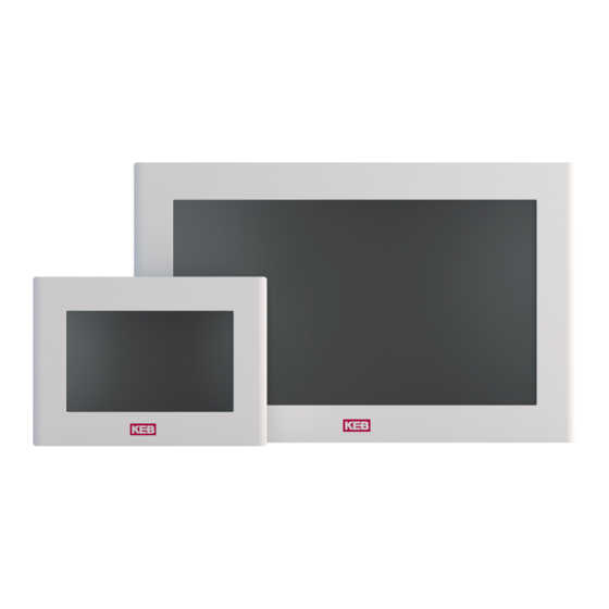
2.4 Configuration The following figures show the va rious configurations. 2.4.1 C6 HMI/C6 HMI LC (full aluminium front panel) Figure 1 C6 HMI / C6 HMI LC 5.7” 4.3” 5.7” 7.0“W 8.4” 10.1” W C6 HMI Full aluminium front panel 10.4”... -
Page 13: Widescreen
2.5.2 Widescreen In the C6 HMI / C6 HMI LC fa mily the systems with 5.7", 8.4", 10.4", 12.1", 15.0" di s - pl a y have a 4:3 a spect ra tio, whereas the s ystems with 4.3", 7.0”W, 10.1”W, 12.1”W a nd 15.6"W display have a aspect ratio of 15:9 or 16:9. -
Page 14: Rear View
2.6 Rear view Figure 4 C6 HMI 4.3” rear view Ventilation holes Mounti ng s eal Figure 5 C6 HMI / C6 HMI LC 5.7” rear view Ventilation holes Mounti ng s eal Note: rear panels may be different de- pending on display size. - Page 15 Figure 7 C6 HMI / C6 HMI LC 8.4” rear view Aera tion holes Mounti ng s eal...
-
Page 16: Side View
2.7 Side view Figure 8 C6 HMI 4.3” side view Aera tion holes Figure 9 C6 HMI 4.3” side view Aera tion holes Recess for fixing clamps... - Page 17 Figure 10 C6 HMI / C6 HMI LC 5.7” side view Aera tion holes Recess for fixing clamps Figure 11 C6 HMI / C6 HMI LC 5.7” side view Aera tion holes Recess for fixing clamps...
-
Page 18: Connection Overview C6 Hmi 4.3
2.8 Connection overview C6 HMI 4.3” Figure 12 C6 HMI 4.3” connections DC supply unit COM TX LED Power on LED COM 1 (RS232/422/485 Slash) USB1 (2.0) LAN1 (100 Mbit/s) Buzzer Reset button COM RX LED 2.8.1 Labels On the rear panel are present the following the connectors l abel. Figure 13 C6 HMI / C6 HMI LC Labelling of the labels... -
Page 19: Connection Overview C6 Hmi / C6 Hmi Lc 5.7" And Higher
2.9 Connection overview C6 HMI / C6 HMI LC 5.7” and higher Figure 14 C6 HMI / C6 HMI LC 5.7” connectors Power DC i nput LAN1 (100 Mbi t/s) Fieldbus USB2 (2.0) LAN2 (10/100 Mbi t/s ) CV connect Res et buttom Power on LED SD ca rd s lot... -
Page 20: Nameplate
2.9.2 Nameplate Figure 16 C6 HMI / C6 HMI LC nameplate details Model UL-Ma rking CE-Ma rki ng Ma terial number Seri al number 2.10 Touchscreen Size Touchscreen Panel technology 4.3” Table 2 4-wire 5.7” Touchscreen 7.0“ W The touchscreen is installed from the back of the 8.4”... -
Page 21: Putting In Operation C6 Hmi / C6 Hmi Lc
2.11 Putting in operation C6 HMI / C6 HMI LC To put i n operation C6 HMI / C6 HMI LC the followings two phases must be done: ● Confi guration and creation of the project of C6 HMI / C6 HMI LC. ●... -
Page 22: Software Options
2.12 Software options COMBIVIS studio HMI COMBIVIS studio HMI Function BASIC for Win CE ADVANCED for Win CE RealTime DB Max. 1024 Byte Max. 4096 Byte Table 3 Scaling Software options ODBC Realtime Trace DB Data structure OPC client DA Networking Graphic interface Vectorial graphic editor... - Page 23 Table 9 Dynamic multilanguage Dynamic multilanguage Unicode support Table 10 Drivers Drivers Max. number of driver PLC tag importer Table 11 Event object Event object Table 12 Scaling object Scaling object Table 13 Scheduler object Scheduler object Logics Table 14 IL Logic (Step5-Step7) Logics VBA Logic (WinWrap Basic)
-
Page 24: Installation And Connection
SECTION Installation and connection... -
Page 25: Preparation For Installation
Check the package content for visible signs of tra nsport damage a nd for compl eteness. In the case of damaged parts, contact your KEB representative. Do not install pa rts damaged during shipment. 3.3 Checking the operating conditions ... -
Page 26: Mounting Position
An i nclined installation reduces the thermal convection by the HMI device a nd the maximum permissible ambient temperature for operation. Pl ease conta ct KEB for details. The HMI device may otherwise be damaged and i ts certifications and war- ra nty wi ll be void. -
Page 27: Checking Installation Distances
3.5 Checking installation distances To ens ure adequate ventilation it is necessary l eaving the following open spaces a round the system: X di rection: (min.) 15 mm for each side. Y di rection: (min.) 50 mm for each side. ... -
Page 28: Degrees Of Protection
3.6.1 Degrees of protection The degrees of protection of the s ystem are guaranteed only if the following condi- ti ons are satisfied: Ma terial thickness a t the mounting cutout for IP66 protection: 2 mm to 4 mm. ... -
Page 29: Mounting The Device
3.7 Mounting the device 3.7.1 Position of the mounting clamps To obta in the declared degree of frontal protection for the s ystem, i t is necessary to res pect the positions of the clamps shown below. The ta ble below s hows the number a nd the position of the clamps for each C6 HMI / C6 HMI LC s i ze. -
Page 30: Tools To Tighten The Mounting Clamps
C6 HMI / C6 HMI LC / 10.4” C6 HMI / C6 HMI LC / 12.1” C6 HMI / C6 HMI LC / 12.1” W C6 HMI / C6 HMI LC / 15.0” C6 HMI / C6 HMI LC / 15.6”... -
Page 31: Procedure
3.7.3 Procedure Ins ert C6 HMI / C6 HMI LC i nto the mounting cutout from the front. Figure 21 Installation Figure 22 Installation... - Page 32 Figure 23 Installation Ins ert the fixing cl amps into the housings of the device. Figure 24 Installation Figure 25 Installation...
- Page 33 Ti ghten the fixing clamps with a 1.5 mm hex key. Figure 26 Installation Note: a dhere to the permissible torque when tightening the threaded pin of the mounting clamp: 0.2 Nm. Figure 27 Installation Repeat steps 2 a nd 3 for all mounting clamps. Check the seal s eat.
-
Page 34: Connecting The Unit
3.8 Connecting the unit 3.8.1 Information for the connection The C6 HMI / C6 HMI LC mus t be installed i n accordance with the data contained i n this i nstruction manual. Thi s units are designed for the connection with a "Secondary Ci rcuit Overvoltage Ca tegory II". -
Page 35: Switching On And Testing The Device
Note Va l ue of tightening torque: 0.22 – 0.25 Nm. Figure 29 Power supply connection details 3.8.3 Switching on and testing the device Connect the power s upply ca ble to C6 HMI / C6 HMI LC. Swi tch on the power supply. Swi tch on the power s upply.The green led will light. -
Page 36: Connecting The Configuration Pc
3.9 Connecting the configuration PC You ca n connect the configuration PC to C6 HMI / C6 HMI LC i n s everal ways: 1) By us ing a Ethernet cross cable connected by one end to the configuration PC a nd on the other end to one of two Ethernet ports of C6 HMI / C6 HMI 2) By connecting C6 HMI / C6 HMI LC to a Ethernet switch on which the config- ura ti on PC a nd C6 HMI / C6 HMI LC a re both connected. - Page 37 Figure 32 Connecting the configuration PC Cl i ck on Ok to save the s ettings. Cl i ck on Start -> Settings -> Control Panel Figure 33 Connecting the configuration PC...
- Page 38 Then double cl ick on “Registry Sa ver” Figure 34 Connecting the configuration PC Cl i ck on the “Save” button and confirm clicking on “Ok”. This operation will s a ve your s etting in a permanent way. Figure 35 Connecting the configuration PC...
-
Page 39: Procedure
3.9.1 Procedure After the connection between C6 HMI / C6 HMI LC a nd the configuration PC, to tra ns- fer the project into C6 HMI / C6 HMI LC you mus t: Sta rt COMBIVIS studio HMI Developing tool. ... - Page 40 Note: the name of the memory ca rd a re according to the following ta ble: Name used by Windows Ex- Note Memory plorer NAND NANDFlash Used internal memory to store the operating Table 24 system. It is a read only memory. Procedure MMCMemory Memory to store data and executables.
-
Page 41: Commissioning The Device
SECTION Commissioning the device... -
Page 42: Memory
4.1 Memory The C6 HMI / C6 HMI LC i s equipped as s tandard with two memories: a NAND flash memory a nd an e -MMC memory ca rd. Purpose of the NAND memory is to s tore the boot l oader (is used during the s tart-up of the C6 HMI / C6 HMI LC), the operating s ys tem and all executable programs. -
Page 43: Slot For Memory Card (From 5.7")
4.3 Slot for memory card (from 5.7") C6 HMI / C6 HMI LC ca n optionally a ccommodate a n SD/SDHC ca rd slot V. 2.0 (push- pus h type). Figure 40 Slot for memory card Slot for memory card memory card (example) 4.4 Installation/removal of a memory card Attenti on: potential data loss... - Page 44 Figure 43 Slot for memory card Pus h the card previously i nserted. Figure 44 Slot for memory card Extra ct the memory ca rd from the slot. Figure 45 Slot for memory card...
-
Page 45: Commissioning A Project
SECTION Commissioning a project... -
Page 46: Combivis Studio Hmi Project
5.1 COMBIVIS studio HMI project 5.1.1 Overview Configuration phase A project includes s creen, alarms, va riables used to represent the real plant of ma- chi ne. The configuration phase is the creation of the project according to the user needs and interaction between the humans and the machine. - Page 47 Cl i ck on Start -> Settings -> Control Panel Figure 46 Configuring the serial port Double click on “Serial Port Configuration” Figure 47 Configuring the serial port Choos e the type of serial communication Figure 48 Configuring the serial port...
-
Page 48: Connecting The Serial Port
A s pecial DB15 connector supports all serial protocols. It is therefore n ecess a ry to a da pt the connections to the technical requirements; KEB ca n s u ppl y co nnecto r a da pters as optional parts but user ca n adapt DB15 connector by himself. -
Page 49: Stopping The Running Project
5.1.6 Stopping the running project Figure 50 Stop running project Pl ease follow these steps to stop a running project: 5. Sel ect TCP i n the upper left list. 6. Ins ert the IP a ddress of the C6 HMI / C6 HMI LC 7. -
Page 50: Starting The Project
5.1.7 Starting the project Picture 52 Starting the project To s ta rt a project in C6 HMI / C6 HMI LC by us i ng the configuration PC you must: 8. Sel ect TCP i n the upper left list 9. -
Page 51: Debugging The Project
5.1.8 Debugging the project You ca n debug the project in C6 HMI / C6 HMI LC by connecting with the configura- ti on PC. In order to be a ble to use the debugging functionality you must prepare your pro- ject a s follows: 1. - Page 52 Figure 54 Debugging the projects The following window will appear. Figure 55 Debugging the project Enter the IP address of the C6 HMI / C6 HMI LC a nd click "OK". A new window opens tha t a sks for the user and the password...
-
Page 53: Transfer The Project From C6 Hmi / C6 Hmi Lc To The Configuration Pc
If the project is not protected, just cl ick the "OK" button, otherwise enter the name a nd password of a project user who has the rights to modify the project. Now you ca n see debugging is starting in COMBIVIS studio HMI on the configuration PC. -
Page 54: Backup And Restore
The C6 HMI / C6 HMI LC ha s tools to backup and restore the contents of its internal memory i n order to manage the project and the operating system of C6 HMI / C6 HMI LC. For further i nformation please contact the KEB Support Center. 5.1.11 Update the operating system... -
Page 55: Combivis Studio 6 Project
5.2 COMBIVIS studio 6 project Thi s chapter is va lid only for C6 HMI LC s ystems which are coming with CONTROL Runti me pre-installed directly from production. 5.2.1 C6 HMI LC – Implementation “CONTROL Runtime” The CONTROL Runtime runs as a thread with “real time” priority. The execution model is based on the “task”... -
Page 56: Preparing The Combivis Studio 6 Programming Environment
5.2.2 Preparing the COMBIVIS studio 6 programming environment The COMBIVIS studio 6 programming environment must be properly configured in order to s upport the code compiler for C6 HMI LC s ystems. You need COMBIVIS studio 6 version 6.2.1.0_3.5.3.50 or a bove i nstalled on the PC. COMBIVIS studio 6 i nstallation can be found in the COMBIVIS studio 6 us er manual. -
Page 57: Transferring The Combivis Studio 6 Application To The Target System
Crea te now a new project a nd i nsert the C6 HMI LC a s new Device as shown i n the fol lowing figure. 5.2.3 Transferring the COMBIVIS studio 6 application to the target system To tra nsfer a va lid COMBIVIS studio 6 a pplication to the Target system, follow these s teps: Ens ure the C6 HMI LC device is connected to the same sub network of the PC where you have running the COMBIVIS studio 6 programming tool... -
Page 58: I/O Feldbus
5.2.4 I/O Feldbus The i mplementation “CONTROL Runtime” for KEB C6 HMI LC s ys tems supports the fol lowing I/O fieldbuses: EtherCAT wi th NO DC s upport (distributed cl ock) on LAN1 Modbus TCP on LAN1 Modbus RTU To i nsert the I/O master right click on the C6 HMI LC device icon on the project tree, s elect “Add Device”... -
Page 59: Support For Retentive Data
5.2.5 Support for retentive data C6 HMI LC s ys tems are equipped with a Mi cro UPS specifically designed to s upport the da ta memory retention. In COMBIVIS studio 6 the retentive va riables can retain their va lue throughout the us ual program run period. - Page 60 The COMBIVIS STUDIO 6 restart behaviour can be configured directly by the user wi th the help of the COMBIVIS STUDIO 6 La unch-Manager program. The La unch-Manager of the CONTROL Runtime is an a pplication stored in the "\MMCMemory\CoDeSys3" folder, a s shown in the following figure. Figure 58 Start CDSlaunchMgr.exe To s ta rt i t, double click on the file name.
-
Page 61: Use In Combination With Combivis Hmi Runtime
5.2.6 Use in combination with COMBIVIS HMI Runtime COMBIVIS HMI Runtime can be of course configured to communicate with the CON- TROL Runtime. The C6 HMI LC i ncl udes the Gateway which is then used as communication inter- fa ce. The COMBIVIS studio HMI project must be configured to communicate with a gener- i c CODESYS controller i nserting i n the “Real Time DB”... - Page 62 The Sta tion must be configured to connect to “localhost”. The device name is the one s hown by the programming s ystem COMBIVIS studio 6 when connected online wi th the C6 HMI LC device from the “Communication settings” window. The CONTROL Runtime running on a C6 HMI LC device can be reached also from a pa nel which has been configured to belong to the same sub network.
-
Page 63: Use In Combination With Combivis Connect
5.2.7 Use in combination with COMBIVIS connect The C6 HMI LC s ys tems are featuring COMBIVIS connect Runtime as preloaded and pre-configured. The COMBIVIS connect VPN connection can be naturally used to connect from re- mote to the CONTROL PLC through the i ntegrated Gateway. Once the VPN i s acti- va ted, just follow the usual s teps to get the online connection. -
Page 64: System-Manager
SECTION System-Manager... - Page 65 The System-Manager is a tool for all ARM and x86 based KEB systems with WinCE operating system. It is available as an integrated component of the op- erating system. The aim of the System-Manager is to provide comprehensive support for sys-...
-
Page 66: Backup Restore
6.1.1 Backup Restore The “Backup Restore” utility interface is shown in the following figure. The program offers two functions: System clone und Restore Selective functions Backup and Restore Note: Before you start the backup or re- store process, the CONTROL Runtime must 6.1.2 System clone und Restore be stopped. - Page 67 Click on "Run" to start the process. You are prompted to specify a path where the clone snapshot should be stored. Note: Target path for the clone file can only be an external memory like a USB stick. As soon as the process has started, the status bar at the bottom of the System- Manager application informs about the running process.
- Page 68 As soon as the process has started, the status bar at the bottom of the System- Manager application informs about the running process. Attention: The backup of the studio HMI application To start the selective backup, click on the button "Backup-features into a .ASR enables the backup of all user applications repository".
-
Page 69: Font Antialiasing
6.1.3 Font Antialiasing The program allows to set the rendering options for the font. Double-click the control panel icon and select the required playback option. Click OK to confirm. Note: The settings are automatically stored in the registry and manual storing is not Font anti-aliasing is only supported by required. -
Page 70: Emmc Usage
Figure 62 Font Antialiasing 6.1.4 EMMC Usage The utility provides useful information about using the eMMC memory together with the status display. Figure 63 EMMC Usage The provided information is divided into current session (since the last reboot) and total (since the system manager utilities were installed). The utility contains the following information. -
Page 71: Kiosk Mode
6.1.5 Kiosk Mode The program allows the activation of the kiosk mode. If activated, the panel directly starts the HMI Runtime with associated project without Windows CE Explorer. Figure 64 Kiosk Mode To activate the kiosk mode, open the utility program and select "Enable kiosk mode"... -
Page 72: Language Settings
Figure 65 Launch Explorer of COMBIVIS studio HMI 6.1.6 Language Settings The program offers fonts for Chinese, Japanese and Korean languages Figure 66 Language settings... -
Page 73: Scrollbar
6.1.7 Scrollbar The program allows the change of the size of the Windows scrollbars. This is useful when creating applications with HMI, because some of the standard con- trols get the scrollbar size information from the operating system. Figure 67 Configure Scrollbar Select the required size of the scrollbars from the window and confirm. -
Page 74: Maintenance
SECTION Maintenance... -
Page 75: Calibration Of The Touchscreen
7.1 Calibration of the touchscreen C6 HMI / C6 HMI LC i s designed to don’t require touchscreen calibration, but i n s ome cases, like update of the operating system, you must recalibrate the touch s creen. To ca l ibrate the touchscreen: ... -
Page 76: Maintenance & Cleaning
Figure 71 Calibration of the touchscreen Cl i ck on the “Recalibrate” button and follow the i nstructions. 7.2 Maintenance & Cleaning C6 HMI / C6 HMI LC i s designed for maintenance-free operation except for the re- pl a cing of the battery backup when necessary. It i s recommended to clean the touchscreen with a damp cl eaning cl oth a nd a display cl eaning solution. -
Page 77: Procedure
7.2.1 Procedure Proceed as follows: a) Swi tch off the HMI device or lock the touchscreen. b) Spra y the cleaning solution onto a cleaning cloth. c) Do not s pray directly onto the display. d) Cl ea n the display from the screen edge inwards. 7.2.2 Backup battery replacement (CR2032 3V) ... - Page 78 The following figures relate to the display models fro m 8.4“ (i nches). Remove the two screws as shown in the figure. Figure 74 Backup battery replacement Remove the two screws as shown in the figure. Figure 75 Backup battery replacement Figure 76 Backup battery replacement...
- Page 79 Loca te the battery position. Figure 77 Backup battery replacement Remove the battery a nd replace i t with one of the same model (CR2032 3V). Figure 78 Backup battery replacement...
-
Page 80: Technical Support & Repairs
Figure 80 Backup battery details 7.3 Technical support & repairs KEB offers wide-ranging, complete a fter-sales technical support. The staff who deal wi th this handle questions on the entire range of products skilfully, quickly, and effi- ci ently. You ca n phone our staff in the service department, a nd they will give you complete, prompt a dvice on how to resolve your problems. -
Page 81: Technical Specifications
SECTION Technical specifications... -
Page 82: Technical S Pecifications
8.1 Technical specifications System software characteristics Integrated system Operating System Microsoft Windows Embedded Compact 7 software (C7P) Table 25 COMBIVIS studio HMI runtimes (Basic, System software characteristics ADVANCED versions) Remote control COMBIVIS connect runtime CONTROL Runtime COMBIVIS studio HMI characteristics BASIC ADVANCED I/O Bytes (tags) - Page 83 400MHz Graphic Controller GPU with integrated LCD controller System memory Type / size / socket 1 GB / DDR3-800 / soldered (contact KEB for dif- ferent memory options) Serial interfaces Type 1 x RS232/422/485 (DB15M) software selectable Optoisolation LAN1 100Mbps (RJ45) with Link/Activity leds...
- Page 84 Electrical characteristics Power supply Type integrated on PC board, auto ranging Table 28 Input voltage 18÷36 VDC with 3-pin plug Electrical characteristics Protection Anti-inversion polarity, overvoltage, soldered fuse on the PC board 500ms of back up time after 7 years of life at an av- Micro UPS erage temperature of 45°C First load: 6 min...
- Page 85 Displays 4.3” LCD size 4.3” Resolution 480 x 272 Colors Backlight Sidelight LED 5.7” LCD size 5.7” Resolution 640 x 480 (VGA) Colors 256K Backlight Sidelight LED 7.0” W LCD size 7” wideband Resolution 800 x 480 (WVGA) Colors Table 31 Backlight Sidelight LED Displays...
-
Page 86: Display Characteristics
8.1.1 4.3” Display characteristics 4.3” Display characteristics Dimensions 4.3” (4:3) Technology TFT active matrix Display area approx. 95.0 (W) x 54.0 (H) mm Resolution 480 x 272 pixel Display color 16 M colors Pixel Pitch 0.198 (W) x 0.198 (H) mm Luminance 400 cd/m (Note 1) -
Page 87: W Display Characteristics
8.1.5 10.1”W Display characteristics 10.1”W Display characteristics Dimensions 10.1”W (16:10) Technology TFT active matrix Display area 216.96 x 135.6 Resolution 1280 x 800 pixel Display color 16M colors Pixel Pitch 0.1695 (W) x 0.1695 (H) mm Table 37 Luminance 400 cd/m 10.1”W Display characteristics ◦... -
Page 88: W Dis Play Characteristics
12.1”W display characteristics 12.1”W Display characteristics Dimensions 12.1" (16:10) Technology TFT active matrix Display area 261.12 x 163.2 Resolution 1280 x 800 pixel Table 40 Display color 16M colors Pixel Pitch 0.204 (W) x 0.204 (H) mm 12.1”W Display characteristics Luminance 400 cd/m ◦... -
Page 89: Certificates And Approvals
8.2 Certificates and approvals Warranty and approvals Emission Conforms to: EN 55022 Information technology equipment – Radio disturb- ance characteristics EN 61000-3-2 Limits for harmonic current emissions EN 61000-3-3 Limitation of voltage fluctuation flicker EMC Directive 2014/30/EU ex 2004/108/EC Immunity Conforms to: EN 55024 Information technology equipment –... -
Page 90: Ports Pinout
8.3 Ports PINOUT 8.3.1 COM1 – DB15M Serial Signal Input/output +5 VDC Transmission data (RS-232) Received data (RS-232) Transmit To Send Clear Tu Send Data set ready Ground Data Terminal Ready Carrier Detect Transmission Data +/Receive Data + (RS-485/RS-422) Input/output Transmission Data -/Receive Data - (RS-485/RS-422) Ring Indication (RS-232) - Page 91 Figure overview Figure 1 C6 HMI / C6 HMI LC 5.7” ............................12 Figure 2 Aluminium front panel details ..........................12 Figure 3 Aluminium front panel details ..........................13 Figure 4 C6 HMI 4.3” rear view ............................... 14 Figure 5 C6 HMI / C6 HMI LC 5.7” rear view........................... 14 Figure 6 C6 HMI / C6 HMI LC 7.0”...
- Page 92 Figure 57 Debug the project ..............................54 Figure 58 Start CDSlaunchMgr.exe ............................60 Figure 59 CDS Launch-Manager .............................. 60 Figure 60 System-Manager system control applets....................... 65 Figure 61 Backup Restore ................................ 66 Figure 62 Font Antialiasing..............................70 Figure 63 EMMC Usage ................................70 Figure 64 Kiosk Mode................................
- Page 93 Table overview Table 1 Packaging ..................................11 Table 2 Touchscreen................................. 20 Table 3 Software options ................................. 22 Table 4 Graphic interface................................. 22 Table 5 Alarm log ..................................22 Table 6 Recipes – Data loggers ............................... 22 Table 7 Trends ..................................22 Table 8 Users &...
- Page 95 Tel: +55 16 31161294 E-Mail: roberto.arias@keb.de Russische Föderation KEB RUS Ltd. China KEB Power Transmission Technology (Shanghai) Co. Ltd. Lesnaya str, house 30 Dzerzhinsky MO No. 435 QianPu Road Chedun Town Songjiang District 140091 Moscow region Russische Föderation 201611 Shanghai P. R. China...
- Page 96 Automation mit Drive www.keb.de KEB Automation KG Südstraße 38 32683 Barntrup Tel. +49 5263 401-0 E-Mail: info@keb.de...
Need help?
Do you have a question about the COMBICONTROL C6 HMI and is the answer not in the manual?
Questions and answers