
Related Manuals for Eneo IAM-6MC1001M0A

Summary of Contents for Eneo IAM-6MC1001M0A
- Page 1 User Manual Ethernet over Coax Transceiver Data/Power supply 270Mbps, 57VDC power input IAM-6MC1001M0A...
- Page 2 Safety instructions • Before switching on and operating the system, first read this safety advice and the operating instructions. • Keep the operating instructions in a safe place for later use. • Installation, commissioning and maintenance of the system may only be carried out by authorised individuals and in accordance with the installation instructions - ensuring that all applicable standards and guidelines are followed.
-
Page 3: Table Of Contents
Contents 1. Quick Installation Guide ................... 3 1.1. Package Contents ...........................3 1.2. Overview ............................3 1.3. Features............................3 1.4. Hardware Overview ........................4 1.5. Product Installation Guide......................5 1.6. Product Application ........................5 1.8. LED Indicators ..........................6 1.9. Specification ..........................6 1.10. Caution ............................7 1.11. Warranty............................7 2. -
Page 4: Quick Installation Guide
1. Quick Installation Guide 1.1. Package Contents DC Cable & EPoC Transceiver Quick Installation Guide DC Terminal Block Quick Start Guide 1.2. Overview This device is a High-Speed, long distance Ethernet & PoE extender that makes possible to transmit IP data up to 2.4Km and PoE up to 1.2Km through various analog cables in different situations. -
Page 5: Hardware Overview
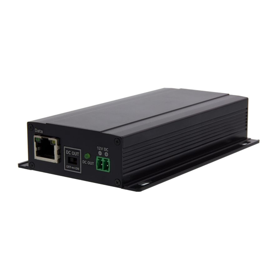
1.4. Hardware Overview Right EPoC Transceiver DC Power Jack Join Button Status LED indicator BNC connector Left EPoC Transceiver RJ45 DC OUT DC OUT LED Terminal Block ON / OFF Switch Note: The Join Button is currently disabled. Quick Installation Guide — 4... -
Page 6: Product Installation Guide
1.5. Product Installation Guide 1. Set the IP address on the camera following the instruction manual of the camera. h If the camera IP is automatically assigned (DHCP, etc.), there is no need to set the camera IP separately. 2. Connect BNC of the coaxial cable to each EPoC Transceiver. 3. -
Page 7: Led Indicators
1.8. LED Indicators Indicator Color Function BNC Join EPoC Devices connected 56VDC input connected Good data connection LINK Poor data connection Quality Good power supply condition Additional adapter required Data Flashes when data is transferred DC OUT DC OUT switch is ON 1.9. -
Page 8: Caution
1.10. Caution • Please install the device following the installation guide. • Do not touch the device and cable with wet hands. • Keep away from moisture and shock. • Do not install near any heat sources such as radiators, heat registers, stoves or other apparatus that produce heat. -
Page 9: Pre-Field Verification
2. Pre-field verification 2.1. Check transmission line 2.1.1. Transmission line type EPoC (Ethernet over Coax) Applicable █ Coaxial cable 2-Wire 3C, 5C, 7C, 10C, RG58, RG59, UTP cable RG6, RG11, KX6, KX100, etc. Ethernet over EPoC Transceiver Coax Transceiver + IAM-4MU1001M0 Pre-field verification —... - Page 10 2.1.2. Check whether the cable is disconnected / shorted Test cable opens █ 1. Make a short the conductor and shield of the one side of the coax. 2. Take the testing probe and connect its cords to the specific ends of multimeter (red positive into the ‘+’ marked jack and black negative into the ‘COM’...
- Page 11 Cable Connection Precautions █ • Be sure to use dedicated connector when connecting cables. • It is not recommended to mix different types of cables. - When 50Ω and 75Ω cable are used in combination or 50Ω BNC is applied to 75Ω cable, the impedance between the lines is unmatched and this could affect performance of the device.
- Page 12 2.1.3. Identify loop resistance • By measuring the loop resistance of the cable, it is possible to check the condition and the quality of the cable used for power transmission function of the EPoC device in advance. 1. Make a short the conductor and 2.
-
Page 13: Check Grounding And Potential Difference
2.2. Check grounding and potential difference EPoC equipment is basically grounded through the power cord of the adapter, so there is no need to ground separately. However, EPoC equipment supports PoC (Power Over Coax) function and the transmitter is powered by the power source connected to the receiver and the end-device is powered by the transmitter through the PoE output feature. -
Page 14: Equipment Installation Guide
3. Equipment Installation Guide 3.1. Selection of installation equipment EPoC Solution Network Security IP Video Surveillance █ EPoC devices allow the coaxial cables from existing analogue CCTV system to be re-used for network camera connection. Reusing existing coax for IP cameras can cut installation costs and save installation time significantly. Analog Camera Coaxial cable D1 : 640 X 480... -
Page 15: Transmission Rate / Poe Output
3.2. Transmission rate Transceiver █ • Transmission rate(Mbps) by product configuration Daisy Chain Distance 200m 600m 1,200m 1,800m 2,400m 3,200m Equipment Installation Guide — 14... -
Page 16: Led Operating Status
3.3. LED operating status 3.3.1. LED status Transceiver █ Indicator Color Function BNC Join EPoC Devices connected 56VDC input connected Good data connection LINK Poor data connection Quality Good power supply condition Additional adapter required Data Flashes when data is transferred DC OUT DC OUT switch is ON Equipment Installation Guide —... -
Page 17: Grounding And Potential Difference
3.4. Grounding and Potential Difference EPoC device is basically grounded through the AC power cord of the adapter, so there is no need to ground separately. If there is a potential difference between the camera(specially metal housing camera) and ground (metal surface), PSE of the EPoC transmitter cannot detect camera’s PD correctly and PoE output will not operate properly. -
Page 18: Troubleshooting Faq
4. Troubleshooting FAQ 4.1. EPoC transmission equipment Problem Action Looking at the features, First, when replacing analog cameras with high-resolution IP camera, you can use the existing Coaxial cable without any special construction. Second, you can supply PoE power or 12VDC to IP camera. As a result, there is no additional power wiring work when installing IP cameras. - Page 19 Problem Action You can use it if the EPoC can supply more power than the maximum power consumption of the IP camera. However, since the power of IP camera is reset when it is below the reference Can I use the 9 VDC, 12 VDC, and 24 value, please use 48~57VDC adapter.
- Page 20 Problem Action This occurs when the video signal is set to low resolution by IP camera. IP camera video is blurred or mosaic Please check if IP camera supports high resolution, encoding method, FPS, occurs. And the image is slow or CBR / VBR, etc.
- Page 21 Problem Action Check the power LED status of Tx EPoC. If the blue LED is not turned on, it could be faulty transmission media or cause of cable length or power consumption of the end-device, or a faulty DC power input. If the blue is on, check the DC OUT switch is On and DC OUT LED status next.
- Page 22 VIDEOR E. Hartig GmbH Exclusive distribution through special- ised trade channels only. VIDEOR E. Hartig GmbH Carl-Zeiss-Straße 8 63322 Rödermark/Germany Tel. +49 (0) 6074 / 888-0 Technical changes reserved Fax +49 (0) 6074 / 888-100 www.videor.com...
Need help?
Do you have a question about the IAM-6MC1001M0A and is the answer not in the manual?
Questions and answers