Table of Contents
Advertisement
Advertisement
Table of Contents

Related Manuals for Alesis M1 Active MKII


Summary of Contents for Alesis M1 Active MKII
- Page 3 ™ REFERENCE MANUAL © 2001-2005 A LESIS ORPORATION...
-
Page 4: Alesis Contact Information
Alesis M1 Active Mk2 Reference Manual © Copyright 2001-2005, Alesis Studio Electronics, Inc. All rights reserved. Reproduction in whole or in part is prohibited. “M1 Active Mk2” and “Superport” are trademarks of Alesis Studio Electronics, Inc. ALESIS CONTACT INFORMATION Alesis Studio Electronics, Inc. -
Page 5: Table Of Contents
Introduction M1 A BOUT THE CTIVE Unpacking and Inspection Inside your new speakers About Nearfield monitoring PEAKER NSTALLATION Avoiding reflections in the studio Stereo nearfield placement of the M1 Active Mk2 Connections Setting the Input Level control ... 31 URROUND OUND About surround sound Center speakers in music mixes... -
Page 6: Introduction
We value any comments you may have about this monitor system, this manual, your Alesis dealer or our factory service. Please take a minute now to fill out your warranty card and tell us what you think. -
Page 7: About The M1 Active Mk2
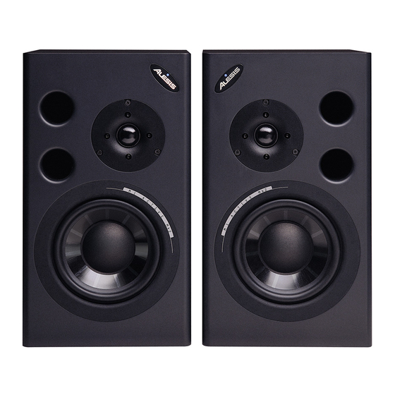
✪ It is important to register your purchase; if you have not already filled out your warranty card and mailed it back to Alesis, please take the time to do so now. The M1 Active Mk2s are designed as mirror-imaged pairs. If you have received a pair where the tweeters are both on the same side, contact your dealer immediately. -
Page 8: Inside Your New Speakers
About the M1 Active Mk2 NSIDE YOUR NEW SPEAKERS ✪ If you’re in a hurry to get started, skip ahead to Chapter 2, “Speaker Installation”, for connection and placement tips. BOUT POWERED MONITORS The M1 Active Mk2s combine a speaker and amplifiers in the same compact cabinet. - Page 9 Therefore, after an initial break-in period, the sound should remain virtually unchanged for the life of the product. Alesis’ proprietary-design tweeter features a special wave guide baffle to improve polar response, a silk dome, and low viscosity ferrofluid formulated specifically to retain the best balance of transient response to power handling.
- Page 10 About the M1 Active Mk2 M1 A CTIVE CROSSOVERS The M1 Active Mk2 uses a 75W woofer amp and a 25W tweeter amp along with 4 order high and low pass electronic crossover filters centered at 2000Hz. Electronic crossovers, which separate the frequencies before being sent to the amplifiers, have fewer phase problems and less power loss than the traditional passive crossover used after the amplifier.
- Page 11 M1 A CTIVE The M1 Active Mk2 employs a regulated switching power supply. This type of supply has previously only been available in amplifiers sold at the very high end of the Pro Audio market. Most power amp customers are familiar with the large transformer and output capacitors in high quality amplifiers.
- Page 12 2KHz-4KHz range. In the tradition of the Alesis Superport design, which uses the energy from the back of the speaker to enhance bass performance, the M1 Active Mk2s use dual, front baffle mounted, long folded ports.
-
Page 13: About Nearfield Monitoring
BOUT EARFIELD MONITORING In the early days of recording, most recording studios used big monitor speakers almost exclusively. Unfortunately, they also required high powered amplifiers and expensive acoustic treatment (often poorly done) of the entire control room. Still, a well-constructed big monitoring system really was impressive to listen to, a fact not overlooked by the studio owners who wanted to impress the record company executives who paid for the big studio's time. - Page 14 About the M1 Active Mk2 M1 Active Reference Manual...
-
Page 15: Speaker Installation
Like any speaker system, your M1 Active Mk2 speakers will work best when properly positioned in a suitable acoustic environment. Achieving proper speaker placement is usually straightforward, but even with nearfield monitors, speaker placement and the acoustics of the listening room itself are too often overlooked and can become significant contributors to an inaccurate and uninspiring monitoring environment. - Page 16 Speaker Installation Monitors placed on the console’s meter bridge can directly radiate back onto the console control panel causing a strong delayed This kind of speaker placement also couples acoustic energy from the speaker's cabinet more readily into the console's chassis. Both conditions should be reduced by placing the speakers on their own stands acoustically detached from, and slightly behind, the console as shown below.
- Page 17 Careful consideration should also be given to the physical spacing between the speakers. Alesis recommends that the distance between the speakers for stereo applications equal the distance between the listener and either speaker. In other words, the listener and the two speakers are at the three corners of a triangle having equal- length sides.
-
Page 18: Stereo Nearfield Placement Of The M1 Active Mk2
Speaker Installation TEREO NEARFIELD PLACEMENT OF THE M1 A CTIVE NOTE: We recommend that the M1 Active Mk2 speakers be placed with the tweeters to the inside , not the outside, of the listening triangle. The “classic” studio monitor layout used to be that the tweeters be placed to the outside of a horizontally-oriented speaker. - Page 19 Speaker Installation ORIZONTAL LACEMENT ECOMMENDATION Traditionally, proper horizontal placement of speaker systems slightly behind (not on) a meter bridge accomplished two purposes: it allowed both woofer and tweeter to be at ear level, and many times, it permitted the recording engineer to see over the speakers and into the studio.
- Page 20 Speaker Installation ERTICAL Vertical placement of the M1 Active Mk2 as shown in Figure 3 is highly recommended. This position will simulate the soundfield that will be heard in most consumers’ homes and (to a great extent) their cars. For this reason, even if the M1 Active Mk2s are positioned horizontally for all of the mixing, the vertical position should always be used in the final "playback check"...
- Page 21 LAYBACK CHECK MODE After you’ve got your mix just right it’s always good practice to perform a “playback check” by standing the M1 Active Mk2s vertically and making the listening triangle larger. The purpose of the playback check is to simulate what your masterpiece will sound like in a “typical”...
- Page 22 Here again, your ear is your most important piece of test equipment. If the subwoofer (such as the Alesis Point One) or preamplifier has 80Hz high-pass filters built-in for connection to the other amplifiers, then no port plugging is necessary.
- Page 23 Speaker Installation M1 Active Mk2 Reference Manual...
-
Page 24: Connections
Speaker Installation ONNECTIONS The M1 Active Mk2 has been designed to be as simple as possible to set up and use. However, please follow the instructions to ensure that you get the best possible performance from your monitors. Before connecting the speakers, make sure the power switches of the M1 Active Mk2s and any equipment they will be connected to are turned OFF. -
Page 25: Power Switch
Speaker Installation OWER SWITCH The POWER switch is located on the back panel. A blue power indicator lamp is on the front panel. NPUT ONNECTIONS Almost any conventional line-level source may be plugged into the M1 Active Mk2’s LINE INPUT jack. The Line Input jack accepts both XLR and 1/4” input plugs wired either balanced or single-ended (unbalanced). -
Page 26: Setting The Input Level Control
Balanced sources often feature XLR outputs. Connect them with an XLR-to- XLR cable. Many consoles (such as the Alesis Studio series) feature balanced outputs on 1/4” jacks; you may use a TRS-to-TRS balanced phone cable, or an XLR-to-1/4 inch phone TRS (tip-ring-sleeve) cable, as shown below. The advantage of using an XLR on the speaker side is that it is a locking connector and cannot be accidentally disconnected. - Page 27 O SET THE LEVEL WITH A MIXER 1. Turn on all system components (the M1 Active Mk2s last) and turn the M1 Active Mk2’s INPUT LEVEL control all the way down. 2. Play program through the mixer and raise the mixer’s fader levels until its meter averages around “0 VU”.
-
Page 28: Avoiding Damage
If you need higher power levels, you are not using the speaker in a near-field application. For extremely loud mid-field and far-field monitoring, we recommend the Alesis Monitor Two speaker with a 300-watt per channel amplifier. Many studios will check recordings on both systems, alternating to avoid ear fatigue and to gain perspective on the mix. -
Page 29: Surround Sound
Powered monitors like the Alesis M1 Active Mk2 Biamplified Reference Monitor have proven to be a simple, cost-effective way to add five-channel surround to control rooms. -
Page 30: Center Speakers In Music Mixes
Surround Sound ENTER SPEAKERS IN MUSIC MIXES In video applications, with left, center and right channels all set to deliver equal output, the ear tends to hear dialog as coming only from the center channel. (It’s a psychoacoustic effect because all right and all left channel signals are fed to the center.) In Dolby Pro Logic, the center channel information is derived from sum and difference information encoded in the left and right channels. -
Page 31: Placement Of The Center M1 Active Mk2 Speaker In The Studio
LACEMENT OF THE CENTER IN THE STUDIO The left, center and right speakers should all be placed in an arc so that the distance of all drivers to the listener is identical (see page 29). The equilateral listening triangle as described earlier for stereo (two-channel) playback should be retained, with the center speaker placed vertically in the center, exactly between the left and right (vertical) M1 Active Mk2s. -
Page 32: Placement Of Rear Surrounds
2) recommendations developed by Tom Holman for setting up THX surround theater sound systems, and 3) Alesis engineers’ experience fine-tuning the performance of the SMS Monitoring System in order to find the mounting configuration which results in the most natural and accurate surround placement. - Page 33 Surround Sound M1 Active Mk2 Reference Manual...
-
Page 34: Wall Mounting
Surround Sound ALL MOUNTING Once your have located the general area for the horizontal and vertical position, you need to find a wall stud. Attach shelving brackets or other commercial speaker-mounting device into the wall stud, then attach the M1 Active Mk2s to the mount, allowing room for the rear-panel input and AC connections. -
Page 35: Mixing For Discrete Six Channel Reproduction Matched Vs Specialized Speakers
IXING FOR DISCRETE SIX CHANNEL REPRODUCTION MATCHED VS SPECIALIZED SPEAKERS While most speaker systems for monitoring music in surround use the same speaker cabinet in all positions, both front and rear, keep in mind that most consumer video surround installations use a different speaker in the rear channels. - Page 36 Surround Sound mid bass (about 80Hz) on up. In the rear go the subwoofers and sometimes, small full range drivers which provide “fill”. So, in essence, today’s best car audio systems are designed to produce an enveloping environment very similar to that of a home theater. The use of M1 Active Mk2s (or any monopolar speaker) as full-range surrounds would be useful in the following cases: •...
-
Page 37: Troubleshootingi
ROUBLESHOOTING If you experience problems while using the M1 Active/Surround systems, please use the following table to locate possible causes and solutions before contacting Alesis Technical Support for assistance. Symptom Hum or buzz No sound Unfocused sound, bass frequencies muddy or missing... -
Page 38: Maintenance
Before contacting Alesis, check all your connections, and make sure you’ve read the manual. Customers in the USA and Canada: If the problem persists, call Alesis USA at 1-800-5-ALESIS and request the Technical Support department. Talk the problem over with one of our technicians; if necessary, you will be given a return order (RO) number and instructions on how to return the unit. - Page 39 Tape a note to the top of the unit describing the problem, include your name and a phone number where Alesis can contact you if necessary, as well as instructions on where you want the product returned. Alesis will pay for standard one-way shipping back to you on any repair covered under the terms of this warranty.
-
Page 40: Specifications
Specifications NCLOSURE ATERIALS AND Front baffle painted in metallic charcoal-gray, one inch (1”) thick MDF with radiused edges to minimize diffraction. Sides and rear baffle covered in metallic charcoal-gray vinyl laminate, over five-eighths inch (0.625”) thick MDF. Dual ports with 45 inlet and flared front baffle outlet allow precise, phase accurate woofer-to-port frequency transition. -
Page 41: Crossover Section
ROSSOVER SECTION Crossover type: Input Impedance: Low Frequency Filter: MPLIFIER ECTION REQUENCY Rated power output: Distortion: Slew rate: Signal-to-Noise ratio: REQUENCY Rated Power Output: Distortion: Slew rate: Signal-to-Noise ratio: COUSTIC ECTION Free-Field Frequency Response: Lower Cutoff Frequency: Upper Cutoff Frequency: Maximum Peak SPL per pair: Maximum short term SPL: ENERAL... -
Page 42: Index
1/4” input plugs, 27 AC cables, 26 AC power, 13, 26, 43 amplifiers, 10, 12, 43 balanced, 27 biamplified, 10 center channel, 32 crossover, 11, 43 frequency response, 43 with ports plugged, 24 front baffle, 42 fuse, 13 Ground loop, 39 grounding, 26 INPUT LEVEL, 28 detent, 29...
Need help?
Do you have a question about the M1 Active MKII and is the answer not in the manual?
Questions and answers