Table of Contents
Advertisement
Quick Links
INSTALLATION INSTRUCTIONS
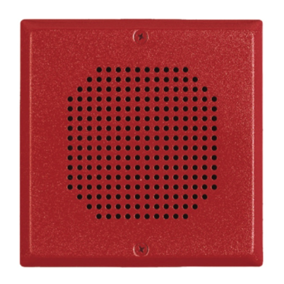
SUPERVISED SELF-AMPLIFIED SPEAKER
(WALL OR CEILING MOUNT)
Use this product according to this instruction manual. Please keep this instruction manual for future reference.
GENERAL:
The Supervised Self-Amplified (SA) Speaker is UL Listed under Standard UL1480 (Speakers for Fire Alarm and Signaling Systems). The
SA Speaker is for indoor fire protection service and provides a choice of 6 different sound output levels and operates with audio input
levels of 0.5 V RMS and 25 V RMS by means of selectable switch settings. The Low Profile design incorporates a high efficiency
speaker for maximum output at minimum power across a frequency range of 400Hz to 4000Hz, and features a sealed back construction
for extra protection and improved audibility. All inputs are polarized for compatibility with standard reverse polarity supervision of circuit
wiring via a Control Panel.
The SA Speaker appliance is listed for indoor use with the backboxes specified in these instructions (see Mounting Options). The SA
Speaker will flush mount onto a 4" square deep backbox with an extension ring, or surface mount using the SBB backbox.
CAUTION: Do not change factory applied finishes. "DO NOT PAINT".
Models
Agency
Speaker DC Input Voltage
Speaker DC Input Current
Audio Input Level
Audio Input Impedance (0.5V setting)
Audio Input Impedance (25V setting)
Environmental
Table 2A: Speaker Sound Pressure Level Ratings
Setting
1
0.5Vrms Audio In
68
25Vrms Audio In
68
Table 2B: Directional Characteristics
-3dB
-6dB
When calculating the total currents: Use Table 1 to determine the highest value of "RMS Current" for an individual appliance, then
multiply these values by the total number of appliances; be sure to add the currents for any other appliances powered by the same source
and include any required safety factors.
Make sure that the total RMS current required required by all appliances that are connected to the system's PRIMARY and SECONDARY
power sources, NAC circuits, DSM Sync Modules or Wheelock Power Supplies does not exceed the power sources' rated capacity or the
current ratings of any fuses on the circuits to which these appliances are wired.
Check the minimum and maximum output of the power supply and standby battery, and subtract the voltage drop from the circuit wiring
resistance to determine the applied voltage to the appliance.
PN P84502E
Table 1: Specifications
SA-S70 (square grille), SA-S90 (round grille)
UL1480
16.0 - 33.0 VDC. "Regulated 24"
0.120 Amps RMS maximum
0.5 V RMS or 25 V RMS (field selectable, Table 3)
Greater than 400 Ohms, or equivalent to less than 1/1000 W (0.001 W
or 1 mW) load
Greater than 20 kOhms, or equivalent to less than 1/32 W (0.03125 W
or 31.25 mW) load
Speaker: 1 to 6 (field selectable, Table 4)
Indoor Use Only. +32°F to 122°F (0°C to +50°C) 93% RH
Reverberant dBA at 10Ft per UL1480
2
3
4
5
71
74
77
81
71
74
77
81
+/- 50 degrees horizontal; +/-50 degrees vertical
+/- 55 degrees horizontal; +/-55 degrees vertical
Copyright 2020 Cooper Wheelock, Inc. dba Cooper Notification
WIRING DIAGRAMS:
FROM PRECEDING
AMPLIFIER OR
SAFEPATH PANEL
1.
Reverberant dBA is a minimum UL rating based on sound measurements in a reverberant test room.
2.
The SA Speaker is not designed to be used on coded systems in which the applied voltage is cycled on and off.
3.
This appliance does not generate a temporal pattern signal. If the distinctive three-pulse temporal pattern Fire Alarm Evacuation (or
6
total evacuation) in accordance with NFPA 72, is required, the control unit must be used with appliances that can generate the
84
temporal pattern signal. Refer to manufacturer's instruction manual for details.
84
+
STROBE
-
+
AUDIO
-
+
POWER
-
Figure 1: SA Speaker Wiring Diagram (Shown with optional-Strobe)
(Wiring must be all power-limited or all non-power-limited)
273 Branchport Ave.
Long Branch, N.J. 07740
(800) 631-2148
www.coopernotification.com
+
-
+
TO NEXT SIGNAL
OR END 0F LINE
RESISTOR
-
+
-
Page 1
Advertisement
Table of Contents

Subscribe to Our Youtube Channel
Summary of Contents for Cooper Notification SA-S70
- Page 1 Check the minimum and maximum output of the power supply and standby battery, and subtract the voltage drop from the circuit wiring resistance to determine the applied voltage to the appliance. PN P84502E Copyright 2020 Cooper Wheelock, Inc. dba Cooper Notification Page 1...
- Page 2 SETTINGS: MOUNTING OPTIONS: The switch on the PCB (SW1) is used to select the input voltage and sound output level, see Figure 3. Figure A: Flush Mount with 4” Square Box & Ext. Ring Figure B: Surface Mount with SBB Figure 2: Figure 3: SLIDE HERE FOR (0N)


Need help?
Do you have a question about the SA-S70 and is the answer not in the manual?
Questions and answers