Advertisement
INSTALLATION INSTRUCTIONS
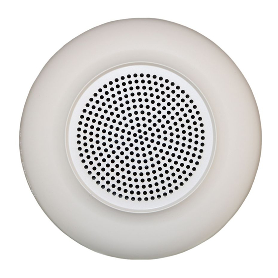
SERIES E60H HI-FIDELITY ROUND
SPEAKERS AND SPEAKER STROBES
Use this product according to this instruction manual. Please keep this instruction manual for future reference.
GENERAL
The Wheelock Series E60H, High Fidelity Round Speakers and Speaker Strobes, are UL Listed under Standard 1971 for Signaling Devices for
the Hearing Impaired, UL Standard 1480 for Speaker Appliances and ULC Listed under Standard CAN/ULC-S541-07 AND CAN/ULC-S526-
07. They are designed for multiple power requirements with high dBA output at each power tap. All models offer a choice of field selectable
taps, 1/8W to 2W, for either 25.0 V
or 70.0 V
audio systems. The design incorporates a high efficiency speaker for maximum output at
RMS
RMS
minimum power across a frequency range of 300-8000Hz. The Series E60H appliances also incorporate a speaker mounting plate attached
to the speaker for ease of installation. The Speaker Strobes can provide a non-synchronized strobe appliance when connected directly to a
Fire Alarm Control Panel (FACP), or provide a synchronized strobe appliance when used in conjunction with a Dual Sync Module (DSM), or
Wheelock power supplies. The strobes use a xenon flashtube with solid state circuitry enclosed in a polycarbonate lens to provide maximum
visibility and reliability for effective visible signaling. The E60H-24MCC and E60H-24MCCH Speaker Strobes are for ceiling mounting only. All
models are Listed for indoor use only with the back boxes specified in these instructions (see Wiring and Mounting Information). 1/8W tap
setting for Private Mode only.
NOTE: All Canadian Installations should be in accordance with the Canadian Standard for the Installation of Fire Alarm Systems - CAN/ULC-
S524 and Canadian Electrical Code, Part 1. Final acceptance is subject to Authorities Having Jurisdiction.
WARNING: Please read these instructions carefully. Failure to comply with any of the following instructions, cautions and warnings
could result in improper application, installation and/or operation of these products in an emergency situation, which could result in
property damage and serious injury or death to you and/or others.
SPECIFICATIONS
Table 1A: UL/ULC Listed Models and Ratings
Model
Voltage
dBA at 10 Feet (Rated Watts)
V
RMS
1/8
¼
E60H
25/70
74
77
E60H-24MCC
25/70
74
77
E60H-24MCCH
25/70
74
77
Table 1B: UL/ULC Listed Models and Ratings
Model
Regulated
Voltage
VDC/V
E60H
----
E60H-24 MCC
24
E60H-24MCCH
24
NOTES
Strobes produce 1 flash per second over the "Regulated Voltage" range.
All models are Listed for indoor use with a temperature range of +32ºF to +120ºF (0ºC to +49ºC) and maximum humidity of 93% RH. The
effect of shipping and storage temperatures shall not adversely affect the performance of the appliance when it is stored in the original
cartons and is not subjected to misuse or abuse.
The maximum supervision voltage is 33 volts DC.
Frequency range of speakers is 300-8000Hz.
CAUTION: Always operate audio amplifiers and speakers within their specified ratings. Excessive input may distort sound quality and may dam-
age audio equipment. Do not exceed 100% of speaker input voltage per UL 1480. Improper input voltage can damage speaker. If distortion is
heard, check for clipping of the audio appliance with an oscilloscope and reduce the amplifier input level or gain level to eliminate any clipping.
WARNING: Candela setting will determine the current draw of the product.
Table 2: Current Ratings with Strobe Only
E60H-MCC/E60H-MCCH Maximum RMS Current (AMPS)
UL Voltage
15cd
DC
16-33VDC
0.065
FWR
16-33V
0.110
RMS
PN P85325A
Speaker
Anechoic dBA
Per CAN/ULC-S541-07
1/2
1
2
1/8
¼
1/2
80
83
85
74
78
80
80
82
85
73
76
79
80
82
85
73
76
79
Strobe
Voltage
Candela
Mounting
Range
Options
VDC/V
RMS
RMS
----
----
A
16-33.0
15/30/75/95
B
16-33.0
115/177
B
30cd
75cd
95cd
115cd
0.105
0.189
0.249
0.300
0.170
0.280
0.375
0.455
Copyright 2012 Cooper Wheelock, Inc. dba Cooper Notification
CAUTION: These strobes are Listed as "Regulated". They are intended to be used with FACPs whose notification circuits are Listed as "Regu-
lated." These appliances shall not be used on UL Listed "Special Application" notification circuits unless the appliances are identified to be
compatible in the installation instructions of the FACP or unless the FACP is identified to be compatible in this instruction manual.
25/70V
WARNING: These strobes were tested to the regulated voltage limits of 16.0-33.0 Volts for 24v models using filtered dc or unfiltered
full-wave-rectified voltage. Do not apply voltage outside of this range.
WARNING: Check the minimum and maximum output of the power supply and standby battery and subtract the voltage drop from
the circuit wiring resistance to determine the applied voltage to the strobes. The maximum wire impedance between strobes shall
not exceed 35 ohms.
CAUTION: Strobes are not designed to be used on coded systems in which the applied voltage is cycled on and off.
WARNING: Make sure the total RMS current required by all appliances that are connected to the system's primary and secondary
power sources, notification appliance circuits, Wheelock dsm sync modules or Wheelock power supplies do not exceed the power
sources' rated capacity or the current ratings of any fuses on the circuits to which these appliances are wired. Overloading power
sources or exceeding fuse ratings could result in loss of power and failure to alert occupants during an emergency, which could
result in property damage and serious injury or death to you and/or others.
WIRING AND MOUNTING INFORMATION
CAUTION: The following figures show the maximum number of field wires (conductors) that can enter the backbox used with each mounting
option. If these limits are exceeded, there may be insufficient space in the backbox to accommodate the field wires and stresses from the
wires could damage the product. Check that the installed product will have sufficient clearance and wiring room prior to installing backboxes
1
2
and conduit, especially if sheathed multiconductor cable or 3/4-inch (1.9-cm) conduit fittings are used.
83
86
82
85
Although the limits shown for each mounting option comply with the National Electrical Code (NEC), Cooper Notification recommends use of
82
85
the largest backbox option shown and the use of approved stranded field wires, whenever possible, to provide additional wiring room for easy
installation and minimum stress on the product from wiring.
NOTE: Wiring method shall be in accordance with CSA C22.1, Canadian Electrical Code, Part 1, Safety Standard for Electrical Installations,
Section 32.
WARNING: Check electrical ratings specified in tables 1 and 2 (as appropriate) to ensure proper input. Be sure that speaker wiring is
connected to speaker terminals only and strobe wiring is connected to strobe terminals only. Check to ensure that wiring at FACP
is correct. Improper electrical input can damage the product or cause it to malfunction, which could result in property damage and
serious injury or death to you and/or others.
177cd
0.420
0.645
Table 3: ULC Directional Characteristics
E60H
-3dBA
+/- 34 degrees horizontal; +/- 17 degrees vertical
-6dBA
+/- 40 degrees horizontal; +/- 32 degrees vertical
A
B
F L U S H M O U N T IN G
F L U S H M O U N T IN G
( S P E A K E R )
( S T R O B E S P E A K E R )
4 " S Q . X 2 - 1 /8 "
B A C K B O X
4 " S Q . X 1 - 1 /2 "
4 " S Q . X 1 - 1 /2 "
E X T E N S IO N R IN G *
E X T E N S IO N R IN G *
# 8 - 3 2 S C R E W S
# 8 - 3 2
S C R E W S
S P E A K E R
M O U N T IN G
P L A T E
R O U N D G R IL L E
MAXIMUM NUMBER OF CONDUCTORS
AWG #18 AWG #16 AWG #14 AWG#12
MAXIMUM NUMBER OF CONDUCTORS
8
8
AWG #18 AWG #16 AWG #14 AWG#12
8
8
8
8
273 Branchport Ave.
Long Branch, N.J. 07740
(800) 631-2148
www.coopernotification.com
4 " S Q . X 2 - 1 /8 "
B A C K B O X
S P E A K E R
M O U N T IN G
P L A T E
R O U N D G R IL L E
8
8
1
Advertisement
Table of Contents

Related Manuals for Cooper Notification Wheelock E60H Series


Summary of Contents for Cooper Notification Wheelock E60H Series
- Page 1 273 Branchport Ave. INSTALLATION INSTRUCTIONS SERIES E60H HI-FIDELITY ROUND Long Branch, N.J. 07740 SPEAKERS AND SPEAKER STROBES (800) 631-2148 www.coopernotification.com Use this product according to this instruction manual. Please keep this instruction manual for future reference. CAUTION: These strobes are Listed as “Regulated”. They are intended to be used with FACPs whose notification circuits are Listed as “Regu- lated.”...
- Page 2 NOTE: The E60H-24MCC comes pre-set at 15cd. NOTE: The E60H-24MCCH comes pre-set at 177cd. WARNING: The candela select switch must be field set to the required candela intensity before installation. When changing the setting of the candela select switch, make certain that it “clicks” in place. After changing the candela setting, the appliance must be retested to verify proper operation.
Need help?
Do you have a question about the Wheelock E60H Series and is the answer not in the manual?
Questions and answers