Table of Contents
Advertisement
Quick Links
PROJECT NAME
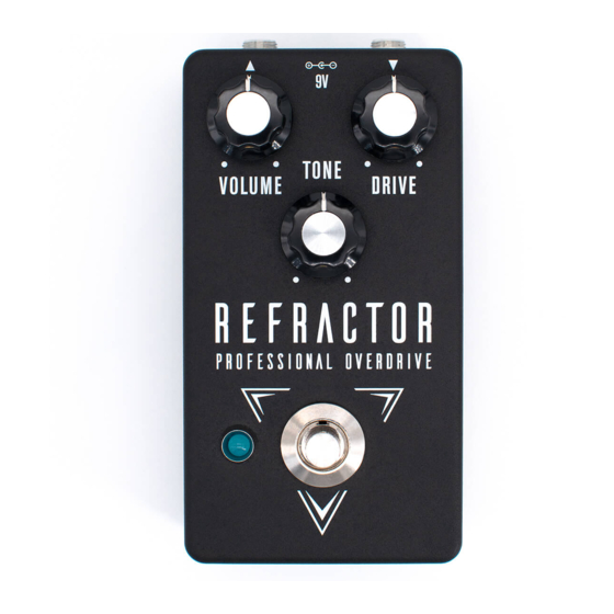
REFRACTOR
BASED ON
Klon Centaur / KTR
EFFECT TYPE
Overdrive
PROJECT SUMMARY
A part-for-part replica of a mythical overdrive effect noted for its high-end tone and price. The Klon
Centaur and its successor, the KTR, remain highly original designs in an industry full of clones and
tweaks to existing circuits.
This documentation is for the kit version of the project. If you purchased the PCB by itself, please
use the
PCB-only version
are completely different due to the specialized parts and assembly methods used in the kit.
REFRACTOR PROFESSIONAL OVERDRIVE
IMPORTANT NOTE
of the documentation instead. The circuit is the same, but the instructions
BUILD DIFFICULTY
Intermediate
DOCUMENT VERSION
1.0.3 (2018-11-22)
1
Advertisement
Table of Contents

Related Manuals for aion REFRACTOR


Summary of Contents for aion REFRACTOR
- Page 1 This documentation is for the kit version of the project. If you purchased the PCB by itself, please use the PCB-only version of the documentation instead. The circuit is the same, but the instructions are completely different due to the specialized parts and assembly methods used in the kit. REFRACTOR PROFESSIONAL OVERDRIVE...
-
Page 2: Table Of Contents
20 Enclosure Layout: Main & Footswitch PCBs 21 Enclosure Layout: Input/Output PCB 22 Final Testing & Assembly 23 Schematic 24 Full Parts List 25 Troubleshooting Information 26 Support & Resale Terms 27 Legal Information & Document Revisions REFRACTOR PROFESSIONAL OVERDRIVE... -
Page 3: Introduction
INTRODUCTION If this is your first pedal, welcome to the hobby and thank you for choosing Aion FX. You’ve just joined a community of over 40,000 people around the world with a passion for building homemade noise machines using obsolete electronics technologies, and we’re glad to have you! If you’ve done this before, it’s great to see you again and we’re confident you’ll find this build experience... - Page 4 Resistors NAME NAME 560R 100n 390n Electrolytic Capacitors NAME 4.7uF 10uF 47uF 100k 100uF 392k 422k Tantalum Capacitors NAME Diodes NAME MLCC Capacitors 1N4001 NAME 1N4742 390pF (marked “391”) 820pF (marked “821”) NAME TL072 TC1044S 8-pin socket REFRACTOR PROFESSIONAL OVERDRIVE...
- Page 5 4-pin wire assembly header D9E germanium diode 9V battery snap DC jack Input/output jack Mounting nut, jack, 0.54" Outer washer, jack, 0.6" Lock washer, jack, 0.5" (thin) Enclosure Enclosure screws PCB, main circuit PCB, footswitch PCB, input/output/DC REFRACTOR PROFESSIONAL OVERDRIVE...
-
Page 6: Tools Needed
The tip should used to tighten the dress nut to avoid lot of pedals! be no more than 0.1” (2.5mm) wide. scratching or denting it (which can happen with metal tools). REFRACTOR PROFESSIONAL OVERDRIVE... -
Page 7: Component Identification
Some voltage regulators It’s recommended to use a also look like this. They may also look like this. razor blade to separate have more than 8 legs. these cleanly. WIRE ASSEMBLY WIRE ASSEMBLY HEADER DC JACK LED BEZEL REFRACTOR PROFESSIONAL OVERDRIVE... -
Page 8: Hardware Identification
MOUNTING NUT DRESS NUT LOCK WASHER DIAMETER: 0.36” / 9.1mm DIAMETER: 0.375” / 9.5mm DIAMETER: 0.4” / 10.1mm FOOTSWITCH MOUNTING NUT DRESS NUT LOCK WASHER DIAMETER: 0.6” / 15.2mm DIAMETER: 0.77” / 19.6mm DIAMETER: 0.6” / 15.2mm REFRACTOR PROFESSIONAL OVERDRIVE... -
Page 9: Main Pcb: Overview
PCB is upside-down, everything is making contact with the work surface and is held in place. So, you will start by populating the resistors (the lowest-profile components), followed by the diodes, sockets, film capacitors, and finally the electrolytic capacitors. REFRACTOR PROFESSIONAL OVERDRIVE... -
Page 10: Main Pcb: Resistors
15 to 20 resistors at a time or the bottom of the board will get too crowded. If this is your first time soldering, watch tutorial videos on YouTube and make sure you get it down before you begin. You don’t want to practice or experiment on this board! REFRACTOR PROFESSIONAL OVERDRIVE... -
Page 11: Main Pcb: Diodes
The germanium diodes included with this kit have been individually tested and verified as working. Unless they arrive damaged, free replacements will not be offered, so please be careful! REFRACTOR PROFESSIONAL OVERDRIVE... -
Page 12: Main Pcb: Sockets & Ics
ICs may have two different orientation marks: either a dot in the upper-left or a half-circle notch in the middle of the top side. Some ICs have both marks. This shows which way the IC should be rotated when inserting it into a socket (the socket also has a half-circle notch). REFRACTOR PROFESSIONAL OVERDRIVE... -
Page 13: Main Pcb: Capacitors (Non-Polarized)
Bend the leads at an angle to hold them in place. MLCCs and box capacitors are not polarized, so they will work in any direction, but to keep things neat, it’s best to put them all facing the same way. REFRACTOR PROFESSIONAL OVERDRIVE... -
Page 14: Main Pcb: Wire Headers
They do fit pretty tightly in the holes, though, so press firmly. There’s also a 4-pin header on the I/O board that we will do in a later step. REFRACTOR PROFESSIONAL OVERDRIVE... -
Page 15: Main Pcb: Capacitors (Polarized)
Like electrolytics, the longer leg still goes in the square pad. These are the last of the on-board components. Now is the time to go back to page 13 and insert the ICs into the sockets. REFRACTOR PROFESSIONAL OVERDRIVE... -
Page 16: Footswitch Pcb
BLUE MARKING Once all three wire assemblies are soldered, set the footswitch PCB aside. We’ll solder the actual footswitch and LED in a later step. REFRACTOR PROFESSIONAL OVERDRIVE... -
Page 17: Input/Output Pcb
Red is positive (+), black is negative (-). After soldering, pull it tight. For even more strain relief, you can thread the snap through the loop to form a knot. (not shown) REFRACTOR PROFESSIONAL OVERDRIVE... -
Page 18: Enclosure Layout: Panel Mounts
You’ll need to hold the bezel in place when OUTER WASHER tightening the nut. Be aware that the bezel is fairly MOUNTING NUT sharp. Try using a rubber band for grip instead of just pressing your finger against the bottom. REFRACTOR PROFESSIONAL OVERDRIVE... -
Page 19: Enclosure Layout: Main & Footswitch Pcbs
However, Aion FX projects are designed to be extremely easy to remove from the enclosure for troubleshooting, with no desoldering required—so with these kits, it’s actually much easier to “box it before you rock it”. -
Page 20: Enclosure Layout: Input/Output Pcb
Note the use of two mounting nuts on each of the jacks, one inside and one outside. The inner nut acts as a spacer to set the DC jack flush with the outside of the enclosure. The inner nuts should be threaded as far down as they can go. MOUNTING NUT OUTER WASHER LOCK WASHER MOUNTING NUT 125B REFRACTOR PROFESSIONAL OVERDRIVE... -
Page 21: Final Testing & Assembly
Last, just close the panel on the back using the four screws. Before that, though, grab a permanent marker and write your name and the completion date on the inside of the back panel. This is an accomplishment! REFRACTOR PROFESSIONAL OVERDRIVE... -
Page 22: Schematic
TRUE BYPASS / BUFFER SLIDE SWITCH VA: 9V PCB IN VB: 18V 1B-1 FROM -VA: -9V BUFFER 100uF 47uF SW1C VR: 4.5V 1N4001 1N4001 INPUT JACK SW1B TC1044 10uF 10uF PWR_GND PWR_GND OUTPUT JACK PWR_GND PWR_GND SW1A FROM EFFECT REFRACTOR PROFESSIONAL OVERDRIVE... -
Page 23: Full Parts List
10uF electro 82n film 4.7uF electro 390pF MLCC 1uF tantalum Diodes Potentiometers Switches PART VALUE PART VALUE PART VALUE PART TL072 Volume 10kB 4PDT slide TL072 Drive 100kB dual 3PDT stomp 1N4001 TC1044S Tone 10kB 1N4001 1N4742A REFRACTOR PROFESSIONAL OVERDRIVE... -
Page 24: Troubleshooting Information
VOLTAGE VOLTAGE VOLTAGE 4.92V 4.96V 9.86V 4.92V 4.92V 5.02V 3V–4V (drifts) 4.91V -9.49V -4.66V 4.90V 4.91V -9.49V 4.92V 4.92V 4.95V 4.97V 4.87V 6.35V 9.86V 17.99V 9.86V REFRACTOR PROFESSIONAL OVERDRIVE... - Page 25 “goop” the PCB or otherwise obscure the source. In other words: you don’t have to go out of your way to advertise the fact that you use Aion FX kits, but please don’t go out of your way to hide it.
- Page 26 These kits are intended to be built by the customer. Aion FX is not responsible for language that may be used by the customer in the marketing or resale of the finished product.
Need help?
Do you have a question about the REFRACTOR and is the answer not in the manual?
Questions and answers