Advertisement
QUICK REFERENCE GUIDE
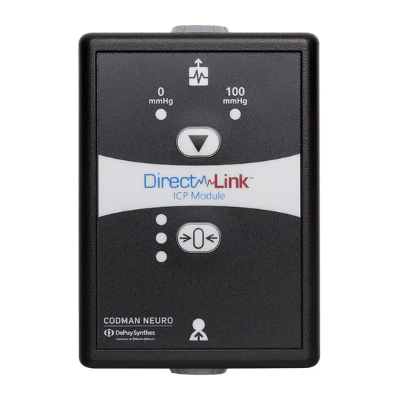
DirectLink® ICP Module
For the Direct Connection of the
Codman Microsensor
®
ICP Transducer
to a Patient Monitoring System
For complete operating instructions, please refer to the manufacturer's user manual
Output Connection
(To Patient Monitor)
Reference Signal
Indicators
Arrow Button
(Patient Monitor
Calibration)
Zero Button
Status Lights
(ICP Sensor Zeroing)
Input Connection
(To Extension Cable & ICP Sensor)
A D I V I S I O N O F I N T EG R A L I F E S C I E N C E S
integralife.com
Advertisement
Table of Contents

Subscribe to Our Youtube Channel
Related Manuals for Integra Codman DirectLink


Summary of Contents for Integra Codman DirectLink
- Page 1 QUICK REFERENCE GUIDE DirectLink® ICP Module For the Direct Connection of the Codman Microsensor ® ICP Transducer to a Patient Monitoring System For complete operating instructions, please refer to the manufacturer’s user manual Output Connection (To Patient Monitor) Reference Signal Indicators Arrow Button (Patient Monitor...
- Page 2 PATIENT MONITOR SETUP Powering the ICP Module & Calibrating to the Patient Monitor Connect DirectLink® ICP Module to the bedside Patient Monitor (PM). Panel lights will flash in sequence during self-test. Wait for SOLID AMBER status light before continuing. Press ARROW BUTTON until the 0 mmHg reference signal indicator illuminates.
- Page 3 ICP SENSOR SETUP Zero the ICP Sensor Prior to Implantation Connect ICP Extension Cable to DirectLink ICP Module. Connect the Codman Microsensor ® Transducer to the ICP Extension Cable. Verify status indicator light is SOLID AMBER prior to continuing. Prepare the Codman Microsensor ICP Transducer for zeroing per the user manual.
- Page 4 DISCONNECTING & RECONNECTING Patient Monitor for Transport and Patient Care Activities An implanted sensor MUST be reconnected to the same DirectLink® ICP Module that was used for zeroing prior to implantation! Failure to do so may result in inaccurate ICP readings. Reconnect DirectLink ICP Module if needed to any compatible patient monitor and follow instructions under PATIENT MONITOR SETUP.
- Page 5 TROUBLESHOOTING SOLID RED LIGHT – MODULE ERROR DETECTED RESET PROCEDURE: Any time the red status light illuminates, the Module must be RESET by disconnecting power. Unplug cable from patient monitor and reconnect to reset. If error occurs during... SELF-TEST: RESET to try again. If problem persists, patient monitor may be incompatible or DirectLink ICP Module needs to be replaced.
- Page 6 TROUBLESHOOTING FLASHING AMBER LIGHT WILL NOT TURN GREEN If error occurs during... SENSOR ZEROING: A non-stable signal was detected from sensor. Verify sensor is not already implanted. An implanted sensor may not be re-zeroed (see “Disconnecting & Reconnecting” section to resume monitoring an implanted sensor).
- Page 7 609-750-4259 fax integralife.com DirectLink, Codman Microsensor, Codman, Integra and Intergra logo are registered trademarks of Integra LifeSciences Corporation or its subsidiaries in the United States and/or other countries. ©2019 Integra LifeSciences Corporation. All rights reserved. Printed in USA. 0M 0810530-2-EN...
Need help?
Do you have a question about the Codman DirectLink and is the answer not in the manual?
Questions and answers