Advertisement
Quick Links
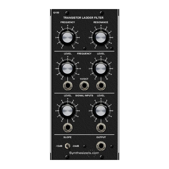
Q150/Q150A Transistor Ladder Filter
Based on Bob Moog's famous design, the Q150 Transistor Ladder Filter
changes the harmonic content of signals to create new, interesting sounds
which is the basis of subtractive synthesis. The cutoff frequency can be
controlled manually and/or controlled by another signal such as an enve-
lope generator, oscillator, keyboard, etc. Frequency control signals can be
attenuated and inverted. Resonance (Q) of the filter is adjusted with a pan-
el control. Both -12dB and -24dB slopes are available.
In most ladder filters the output signal is greatly reduced as the resonance
is increased. This usually requires resetting input levels (sometimes many)
when changing resonance settings - quite annoying. Special circuitry in the
Q150 keeps the output signal level at various resonance settings while
keeping the harmonic content unchanged. This option can be disabled with
a jumper if desired.
The Q150A is a single-wide version with only one attenuated input and
one frequency voltage control. The frequency voltage control can be
changed from reversable to attenuated by moving the pot and jack con-
nectors on the pcb.
Specifications
Q150 Panel Size: Dual width 4.25"w x 8.75"h.
Q150A Panel Size: Single width, 2.125"w x 8.75"h
Low Pass Slope: -12dB/Oct or -24dB/Octave.
Cutoff Frequency: 1/V per Octave and adjustable.
Resonance (Q): 1 to self-oscillation.
Frequency Range: 20hz to 20khz.
Power: +15V@30ma, -15V@30ma.
Waveform Levels: 10V PP.
Dec 2018
Advertisement

Related Manuals for Synthesizers.com Q150


Summary of Contents for Synthesizers.com Q150
- Page 1 Q150/Q150A Transistor Ladder Filter Based on Bob Moog's famous design, the Q150 Transistor Ladder Filter changes the harmonic content of signals to create new, interesting sounds which is the basis of subtractive synthesis. The cutoff frequency can be controlled manually and/or controlled by another signal such as an enve- lope generator, oscillator, keyboard, etc.
- Page 2 Q150/Q150A Transistor Ladder Filter Filter cutoff Manual frequency manual resonance (Q) adjustment control Filter cuttoff frequency voltage controls. One is reversable, one attenuated, one is 1V/Oct to track keyboard. Signal input mixer with manual attenuation Slope Control Filtered signal -24dB is the...
- Page 3 Q150/Q150A Transistor Ladder Filter Filter cutoff frequency manual adjustment Filter cutoff frequency voltage controls. reversable is preselected, Attenuated can be set on pcb, Use 1V/Oct to track keyboard. Manual resonance (Q) control Signal input mixer with manual attenuation Slope Control...
-
Page 4: Controls And Connectors
Q150/Q150A Transistor Ladder Filter Controls and Connectors Manual Frequency and Resonance Control Section Frequency Control Manually controls the filter's cutoff frequency. Resonance Control Manually control of the filter’s resonance. Frequency Control Section Frequency Level Controls Allows adjustment of the cutoff frequency control input. - Page 5 These additional frequencies are called harmonics and different waveforms have different amounts. The Q150 Filter changes the way a waveform sounds by attenuating (lowering the amplitude) of these harmonics. This effect is especially useful when changing over time.
-
Page 6: Pc Board Layout
Q150/Q150A Transistor Ladder Filter Calibration Calibration is accomplished with two trim pots. The Tracking trim pot is the one closest to the power con- nector. The Resonance trim pot is near the center of the board. * Setup Turn resonance to 10, Slope: -24dB.
Need help?
Do you have a question about the Q150 and is the answer not in the manual?
Questions and answers