Advertisement
Quick Links
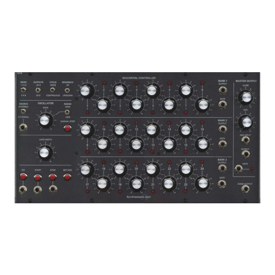
Q119
Sequential Controller
Aug 2014
The Q119 Sequential Controller (Sequencer) creates a series of signals at a rate determined by an inter-
nal oscillator or external source. Normally used to create loops of sounds, effects, arpeggios, or complex
envelopes.
Operation
Stages and Banks
The sequential controller can be configured as one bank of 24 stages, or 3 individual banks of 8 stages
each. Each bank has its own voltage output which is set manually, and a gate output. The output voltage
range is selectable: 0/+5 volts or -5/+5 volts. An LED indicates which stage is active.
Master Output
A master output is also provided that adds features including Glissando also known as Portamento or
slew limiting, manual voltage adding, and external voltage adding, and an LED indicating the Gate output
status. When in 3x8 mode (3 banks of 8 stages) the master output adds together voltages from the three
output banks.
Gate Outputs
Each Bank has its own gate output (normally only used when in 3x8 mode), and there is a master gate
output (normally only used when in 1x24 mode). The width of these gate signals are determined by a
single front panel control. The width can be controlled from approximately 10% to 90% of the stage's on
time. Individual gate outputs for each stage are not provided.
Triggering
The sequential controller can be triggered (started and stopped) manually or by external triggers from
oscillators, envelope generators, keyboard gates, etc. Several options exist including a level sensitive
'Go' input that causes the sequencer to start on the rising edge of a signal and stop on the falling edge.
The 'Start' and 'Stop' signals can be used to control the sequencer with individual signals for each, or in
conjunction with the 'Go' signal. This configuration gives you great control over how the sequencer be-
haves. For example: if you would like the sequencer to only be on when a key is pressed from the key-
board, connect the keyboard's gate output into the 'Go' input. If you would like the sequencer to start,
simply press the 'Start' button. To create 3 complex envelopes in response to a key press, select 3x8
mode, and connect the keyboard's gate output into the 'Start' input, and set the 'Cycle' switch to 'Once'.
Advertisement

Related Manuals for Synthesizers.com Q119


Summary of Contents for Synthesizers.com Q119
- Page 1 Q119 Sequential Controller Aug 2014 The Q119 Sequential Controller (Sequencer) creates a series of signals at a rate determined by an inter- nal oscillator or external source. Normally used to create loops of sounds, effects, arpeggios, or complex envelopes. Operation...
- Page 2 Q119 Sequential Controller Aug 2014 Oscillator Control Section. Speed control and internal/ external selection. Output Section Use square wave or gate. for 24-stage mode. Manual Stepping. Glide speed. Mode Control Section. ADD knob offsets the 8-stage or 24-stage. output voltage Output range contrl.
- Page 3 Q119 Sequential Controller Aug 2014 Operation continued… Continue or Reset Mode The default power-up mode is 'Reset'. Whenever the sequencer is triggered with the 'Go' or 'Start' sig- nals, the sequence will reset to stage 1 and start. There is a special, somewhat hidden mode called 'Continue' mode that can be toggled by holding the 'Set End' button and pressing the 'Manual Step' button once.
- Page 4 Q119 Sequential Controller Aug 2014 Controls and Connectors continued... Cycle Switch Causes the sequencer to cycle once or continuously. Receiving a ‘Go’ or ‘Start’ signal will restart the se- quence at stage 1. Sequence Switch Choose between an up only sequence: 1,2,3… , or up/down 1,2,3….3,2,1.
- Page 5 Q119 Sequential Controller Aug 2014 Controls and Connectors continued... Stop Button / Connector This is a rising edge-sensitive signal used to stop the sequencer. Pressing this button (holding it is not necessary) or applying a signal will cause the sequence to stop. The threshold of this signal is approxi- mately 1.5 volts.
-
Page 6: Specifications
Q119 Sequential Controller Aug 2014 Specifications Panel Size: Octal width 17"w x 8.75"h. Gate Signals: 0-5 volts active high. Output Voltage Levels: 10V PP. Control Input Levels: 0-5V. Internal Oscillator: 2 to 200hz. External Oscillator Speed: 1Khz maximum. Gate Width Adjustment: 10% to 90% of stage On time. - Page 7 Q119 Sequential Controller Aug 2014 PC Board Layout...
Need help?
Do you have a question about the Q119 and is the answer not in the manual?
Questions and answers