Table of Contents
Advertisement
Quick Links
Advertisement
Table of Contents

Related Manuals for GHL ProfiLux 4


Summary of Contents for GHL ProfiLux 4
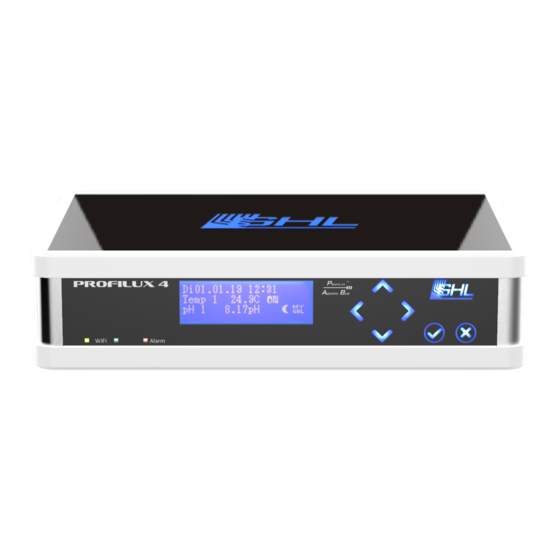
- Page 1 ProfiLux 4 / 4e Instruction Manual As of 2019-02-01...
-
Page 2: Table Of Contents
5.7.1 What is the PAB ............................23 5.7.2 How does the ProfiLux Aquatic Bus work ....................23 5.7.3 Exemplary Connection of ProfiLux 4 / 4e with PAB Devices ..............24 ........................24 ONNECTION TO THE OWER UPPLY 4 / 4 ...................... - Page 3 Instruction Manual ProfiLux 4 / 4e 5.9.2 WiFi Status LEDs on the Front Panel ......................26 OPERATION ..............................28 ............................ 28 PERATION ON THE EVICE 6.1.1 Menu Structure ............................30 6.1.2 Display Indications ........................... 31 6.1.3 Standard Display ............................. 32 6.1.4...
- Page 4 Thank you for purchasing our product and allowing us to help support your path to successful fishkeeping! With a GHL ProfiLux 4 / 4e, you now own a highly professional piece of equipment that is more than capable of assisting you in your daily monitoring and maintenance routines.
-
Page 5: Get The Most Out Of Your Ghl Product
These and other helpful documents can be downloaded from our website’s download area (Support->Downloads). Visit our homepage at www.aquariumcomputer.com, our Knowledge Base or our Support Forum or meet us on Facebook to become a GHL- Product expert and fully utilize the full range of functions offered from your device! 1 Safety Instructions Please read these instructions carefully before operating the ProfiLux 4 /4e. -
Page 6: Safety Of Children And Vulnerable Persons
• 1.2 Intended Use The ProfiLux 4 / 4e is intended exclusively for use in the domestic area. ProfiLux 4 / 4e may only be operated with GHL accessories. Make sure to place the device away from splashing water, moisture or other liquids. -
Page 7: General
For your own safety, please look at the hazard prevention and safety instructions in the chapters that follow. 2 General 2.1 About this Manual These instructions apply to the Controller ProfiLux 4 / 4e. 2.2 Features Illuminated blue graphical display •... -
Page 8: Scope Of Delivery
• Please check to make sure all items are in perfect condition. In case of damage, immediately contact the dealer from whom you purchased the ProfiLux 4 / 4e. WARNING Damaged ProfiLux 4 4e controllers or components may not be put into operation under any circumstances. -
Page 9: Connection Overview
A repair caused by this, is not covered under warranty and will • therefore incur repair charges. 3.2 3.2 Connection Overview The total of all available inputs and outputs in the ProfiLux 4 / 4e is referred to as resources. The ProfiLux 4 controller includes the following connection ports: 2019-01-22... -
Page 10: Sensor Inputs
The default function of each sensor input corresponds to the first- mentioned sensor input label at the back of the ProfiLux 4 / 4e. For example, if an input is labeled, pH / redox, the sensor input is by default, adjusted to pH. If it is labeled, Redox / pH, the sensor input is set to Redox, etc. -
Page 11: Powerbar Connection (Profilux 4 Only)
PC using an additional special GHL RS232 cable. 3.2.4 Expansion Slots The ProfiLux 4 / 4e allows you to modularly expand upon the existing system by using the 3 on-board Expansion Card slots. If you wish to add additional sensors, powerbars, dimmable lamps, etc, you can install up to 2 ProfiLux Expansion Cards. -
Page 12: Level Sensor Connections
3.2.11 DCF Receiver Connection A DCF77 Receiver from GHL can be connected to this RJ10 Western socket. The DCF Receiver must be activated so that ProfiLux 4 / 4e is able to decode and use the time transferred from the receiver. -
Page 13: Aux Connection
4 Functions of the ProfiLux 4 / 4e 4.1 Functionality of the ProfiLux 4 / 4e ProfiLux 4 / 4e can reliably and accurately measure and control all the important parameters and thus help you in obtaining the sensitive biological balance in your aquarium, terrarium or pond. -
Page 14: Functions
Instruction Manual ProfiLux 4 / 4e The highly accurate pH control electronics can down regulate (e.g. CO2 supply) or up regulate (Alkalization) based on the programming that is made. Disabling pH control during the night can also be programed. For measuring and controlling, you will... - Page 15 Integrated webserver: Display of values and states, change of important settings, • email client, DHCP USB and WiFi • Cloud service myGHL® • Connection options for GHL Control Pad, Power-Failure-Monitor, AUX • Connectivity for radio-controlled clock receiver (DCF) • Programmable reminders • Control of 64 switchable sockets and dosing pumps •...
-
Page 16: Activation
5.2 Important Operating Instructions ProfiLux 4 / 4e as well as its accessories (e.g. Powerbar) are destroyed by excess moisture or too high atmospheric humidity - Please observe the technical data and... - Page 17 Additional sensor cable extensions (BNC2 or VTN cables) and PAB • cables are available in different lengths to fit your needs. They are available online in our GHL Store (For US customers, GHL USA Store). WARNING To ensure proper operation, the connection cables should never be •...
-
Page 18: Connecting The Sensors
This may cause malfunction or damage the connected products and the ProfiLux 4 / 4e. They should only be pulled by the plug connected to the power socket. ProfiLux 4 / 4e and its accessories are destroyed by moisture or excessive humidity. 5.3 Connecting the Sensors Connect the sensor connection cables into the corresponding connector sockets provided for the specific purpose. -
Page 19: Connecting Powerbars To Profilux 4 / 4E
5.4 Connecting Powerbars to ProfiLux 4 / 4e For switching electrical loads with the ProfiLux 4 / 4e, you need a Powerbar, which is not included in the scope of delivery of the controller. The following Powerbar options are available: STDL4-4 •... -
Page 20: Powerbar 6D
Powerbar 6D can be daisy-chained). The microprocessor control offers additional security features. WARNING If you want to use a Digital Powerbar (Non-PAB) with the ProfiLux 4, • the corresponding S-socket in the ProfiLux 4 must be activated before any programming takes place. -
Page 21: Powerbar5.1-Pab
Yellow Western sockets of the ProfiLux 4. GHL luminaires do not need to be connected to the STDL4-4 Powerbar, they are instead connected to a permanently live socket since the on/off switching of GHL luminaires takes place via the control cable. -
Page 22: Connecting The Mitras Lightbar Or The Mitras Slimline
The control cable of the Mitras Lightbar is plugged directly into the Black Mitras Lightbar RJ 12 socket provided for this purpose. Illumination Runs as well as lighting projects can be conveniently programmed via the GHL Connect platform (iOS & Android App, Cloud myGHL, Webserver) or PC-software GHL-Control- Center (GCC). -
Page 23: Connection Of Pab-Devices
Instruction Manual ProfiLux 4 / 4e The exact procedure can be found in the "Programming manual ProfiLux 4" for download in the download area of our homepage www.aquariencomputer.com. 5.7 Connection of PAB-Devices The ProfiLux 4 / 4e includes two PAB-ports for connecting additional ProfiLux Aquatic Bus compatible devices. -
Page 24: Exemplary Connection Of Profilux 4 / 4E With Pab Devices
5.8 Connection to the Power Supply Connect the ProfiLux 4 / 4e using the supplied power adapter to the power supply. Insert the DC plug into the designated 12 V DC hollow socket on the rear panel and connect the power connection cable with the plug to the power outlet. -
Page 25: Status Indicators Of The Profilux 4 / 4E
5.9 Status Indicators of the ProfiLux 4 / 4e The ProfiLux 4 includes two status indicator lights which are located on the housing cover and the front of the device. 5.9.1 System-Status- LED on the housing cover The LED-backlit GHL Logo in the housing cover of the ProfiLux 4 / 4e lights up in different colors. -
Page 26: Wifi Status Leds On The Front Panel
Instruction Manual ProfiLux 4 / 4e 5.9.2 WiFi Status LEDs on the Front Panel Located on the front panel of the ProfiLux 4 / 4e next to the red Alarm LED are another two LEDs that provide information about WIFI connection and communication. - Page 27 Instruction Manual ProfiLux 4 / 4e DANGER Never leave your aquarium or terrarium unsupervised for an • extended amount of time. The ProfiLux-System can assist you with many tasks and inform you • about error conditions (For example, via email or SMS) - it can in no- way, replace regular personal supervision and on-site checks-ins.
-
Page 28: Operation
Instruction Manual ProfiLux 4 / 4e 6 Operation 6.1 Operation on the Device Use the navigation buttons (arrow keys) on the device to make settings or desired changes to your settings. Set the time and date first. If you have connected the optional DCF module (radio clock receiver), “Use DCF” is activated and the DCF signal can be received, the time and date are set automatically after the power supply is connected. - Page 29 Instruction Manual ProfiLux 4 / 4e stored in the nonvolatile memory (FRAM, independent of the mains voltage) and are restored after voltage interruption. The following types of dialogs are used when operating the device:: Dialog type Display* Operation Use the left-arrow key to select Yes, use the right-arrow key to select No.
-
Page 30: Menu Structure
Instruction Manual ProfiLux 4 / 4e 6.1.1 Menu Structure The operating menu is structured as follows: Menu Structure* Date & Time Reminder Clock: Timer Dosing pump Location Illumination: Illumination run Shift curves Manual illumination Clouds Moon Rainy days Burning in... -
Page 31: Display Indications
If there is no alarm, the display shows the day, date and time in the upper line. On the right side of the display, different symbols are displayed depending on the operating state: Display Meaning ProfiLux 4 displays an alarm. Check immediately the system! Maintenance mode active Feeding pause active Current lunar phase... -
Page 32: Standard Display
Instruction Manual ProfiLux 4 / 4e The lower lines display current values, e.g. brightness of an illumination channel or lunar phase, state of stream pumps or temperature. The viewable data can be freely adjusted as needed. The basic setting does not display all the values described below. -
Page 33: Feeding Pause
6.2.1 Requirements Step 1: Download the GHL Connect app on your smartphone or tablet. GHL Connect is a free app available for download on the Google Play Store (Android) or Apple iTunes (iOS). Search: GHL CONNECT Download the app, but do not open it just yet. -
Page 34: General Settings Setup
Some flashing of this LED is normal. Step 3: Open GHL Connect app, select Add device, select the ProfiLux 4 / 4e, give this connection any name (P4 hotspot), leave other fields as-is, press Add, select the newly made connection. -
Page 35: Hotspot Setup
OPTIONAL: If you wish to have an audible alarm only at certain times of the day, you can activate that feature in the Alarm section. The brightness of the GHL –logo can also be adjusted. If you wish to set a custom PIN to prevent unauthorized access, you can do so in the Security section. -
Page 36: Assign Pab-Devices
Step 5: Use your device to search again for nearby networks, select the NEW name of the hotspot network and connect to it. Enter the password you assigned when prompted. Once connected, open the GHL Connect app and connect to your device. NOTE: When searching for nearby Wi-Fi networks, you should now see the new name of your P4 / P4e’s hotspot network. -
Page 37: Wi-Fi Setup - Adding The P4/4E To Your Network
Instruction Manual ProfiLux 4 / 4e 6.2.5 WI-FI Setup – Adding the P4/4e to your network Step 1: Connect to your P4 / P4e’s hotspot signal, press menu icon (top left), select Network, and select Client. In the SSID field, type-in the EXACT name of your Wi-Fi network (case sensitive). -
Page 38: Operating The Device Via The Software Gcc
6.3.2 GCC General Information With the Load button, the settings of the ProfiLux 4 are read out and the program displays are updated. With Save, the settings you have made in the program are transferred to the device. -
Page 39: Connection Between The Profilux 4 / 4E And Pc
The PC program GCC must be set up • Open the application and connect to your device. Via "Administration" -> "Connections" -> "Device Manager" you first get the "GHL Virtual Communications Port" for your device. In the illustrated example, this is "COM4". - Page 40 For further settings and programming, e.g. of the Powerbar, please refer to the "Programming manual for aquarium computers model ProfiLux 4 " which you can download in the download area (Support-> Downloads) of our homepage www.aquariumcomputer.com.
- Page 41 Otherwise your changes will not be transferred to the device. If your ProfiLux is connected to GCC and you make settings directly on your ProfiLux 4 at the same time, you have to transfer these to the GCC by pressing the "Update view" button.
-
Page 42: Save And Load Settings
6.5.1 Saving Settings Settings of the connected ProfiLux 4 / 4e or sensor data (= settings of the controllers and calibration data) of ProfiLux 4 / 4e are stored in a file (File name .par). -
Page 43: Measurement Data
With Read & Save, all new existing measurement data is read out of the ProfiLux and is written into a text-file. ProfiLux 4 stores the time of the recording so that the same data is not collected several times. Before saving you have the possibility to set some formats for the data export. - Page 44 If you wish to add an Expansion Card, please read the following instructions before you start: WARNING If ProfiLux 4 / 4e is already in operation, pull the power plug and • remove all sensors and PAB cables. Please prevent damage to internal electronics by avoiding static •...
-
Page 45: Installation
Instruction Manual ProfiLux 4 / 4e 7.2 Installation 7.2.1 How to Open the Housing Turn ProfiLux 4 / 4e upside down and carefully loosen the 4 Allen screws in the 4 corners of the housing bottom plate. Pull the screws out and reverse the housing together with the bottom plate again. -
Page 46: How To Insert Modules
Instruction Manual ProfiLux 4 / 4e You can further extend ProfiLux 4 / 4e with an additional Expansion Box 2 and include even more resources such as sensor connections, 1-10 V interfaces and switching outputs On the right, the empty slots for plugging in the modules are seen in the illustration above. -
Page 47: Restart
Restart the ProfiLux 4 / 4e in compliance with the following instructions. 7.2.4 Restart Connect the sensors as well as the PAB cables to the ProfiLux 4 / 4e and restore the power supply again. Before restarting please observe the following precautions:... -
Page 48: Additional Information
"Transfer from file to ProfiLux". For the update, you need the latest firmware and the PC program GHL Control Center, both of which can be downloaded free of charge from our homepage www.aquariumcomputer.com... - Page 49 BNC-input for Conductivity sensor, , in fresh water accuracy Conductivity measurement 1 µS, measurement range 0 µs to 2000 µS, in salt water accuracy 0.1 mS, 0 mS to 100 mS (ProfiLux 4 only) BNC input for Redox sensor, accuracy 1 mV, measurement Redox measurement range -1000 mV to 1000 mV BNC input for oxygen sensor, accuracy 0.1%, measurement...
Need help?
Do you have a question about the ProfiLux 4 and is the answer not in the manual?
Questions and answers