Table of Contents
Advertisement
Quick Links
Instruction Manual
MCK-1023
March 2009
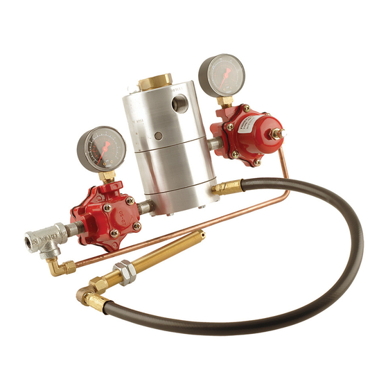
Type n201 automatic Cylinder Filling Valve
Warning
!
install, use, and maintain this equipment
according to manufacturer's instructions
and all federal, state, local laws and
codes, and nFPa Pamphlet 58. Periodic
inspection and maintenance is essential.
introduction
Type N201 automatic cylinder filling valve is supplied
completely piped up, and consists of a filler valve
assembly, two Type 67 regulators with pressure
gauges, a trip valve, and special parts for alternate
scale installations.
Principle of Operation
Refer to Figure 2. Supply pressure registers at
regulators 1 and 2. Pressure from regulator 1
registers beneath the lower diaphragm of the filler
valve, see "A" in Figure 2. This pressure holds the
lower valve closed, preventing pressure from regulator
2 from registering on the upper diaphragm. Spring
force holds the upper valve open, and liquid from the
charging pump can enter the cylinder to be filled.
When the cylinder reaches the predetermined weight
set on the scale, the beam button on the scale beam
contacts the trip valve, see "B" in Figure 2. The trip
valve opens to exhaust pressure from under the
lower diaphragm. Spring force opens the lower valve,
allowing pressure from regulator 2 to register on the
upper diaphragm. This closes the upper valve, and
stops flow through the orifice. A red button indicates
that the filler valve is closed and that the cylinder is full.
Removing the full cylinder from the scale closes the trip
valve and permits the system to reset itself for the
next cylinder.
P1090
installation
Refer to Figure 3.
1. Connect the top 1/2 FNPT connection "C" of
2. Determine if the trip valve hose is long enough to
3. Standard trip valve installation (also see alternate
www.emersonprocess.com/regulators/lp
Figure 1. Type N201 Automatic Cylinder Filling Valve
the filler valve to the charging manifold.
reach the scale frame as shown. If not, insert
1/8-inch (3,2 mm) pipe as needed.
methods, 3.A and 3.B):
a. The trip valve should be installed at
approximately 1/5 of the scale beam length,
measured from the pivot point to the beam
stop. Although the trip valve can be installed
to operate directly off the scale beam, it is not
recommended because of the side play in
most scale beams can resuIt in failure to
contact the trip valve.
Type N201
Advertisement
Table of Contents

Related Manuals for Emerson Fisher N201 Series


Summary of Contents for Emerson Fisher N201 Series
- Page 1 Type N201 Instruction Manual MCK-1023 March 2009 Type n201 automatic Cylinder Filling Valve Warning install, use, and maintain this equipment according to manufacturer’s instructions and all federal, state, local laws and codes, and nFPa Pamphlet 58. Periodic inspection and maintenance is essential. introduction Type N201 automatic cylinder filling valve is supplied completely piped up, and consists of a filler valve...
- Page 2 Type N201 FrOm Charging PumP FrOm Charging PumP sCalE FramE sCalE FramE TriP ValVE BEam BuTTOn sCalE BEam suPPly PrEssurE FillEr suPPly ValVE PrEssurE FillEr ValVE a. Filling CylinDEr B. Full CylinDEr Figure 2. Operational Schematic b. Drill a 5/8-inch (16 mm) hole through the scale 3.A On installations where the slide weight “H”...
- Page 3 Type N201 FrOm Charging PumP aPPrOX. 1/5 maniFOlD TriP ValVE lEngTh OF sCalE FramE hOsE sCalE BEam sTanDarD TriP ValVE TyPE n201 TriP ValVE insTallaTiOn PilOT VaPOr FillEr ValVE PrEssurE FrOm air COmPrEssOr sTOragE TanK, 2 PiVOT sCalE BEam Or auXiliary POinT BEam sTOP PrOPanE CylinDEr...
- Page 4 Type N201 note Table 1. Maximum Supply Pressure and Maximum Recommended Pump Discharge When operating with high pump minimum suPPly maXimum rECOmmEnDED PumP pressure, the filler valve may close off, PrEssurE, Psig (bar) DisChargE, Psig (bar) then reopen for a short spurt and close 21 (1,4) 200 (13,8) off again.
- Page 5 Type N201 17 16 14 32 35 CH1624 BuTTOn anD Bar FOr aTTaChmEnT TO sCalE BEam Figure 4. Type N201 Assemblies...
- Page 6 Type N201 TyPE 67CW-684 CH1624 TyPE 67CW-685 Figure 4. Type N201 Assemblies (continued) 5. Remove orifice (key 3) and unscrew the disk 3. Replace disk holder assembly (key 5) and holder assembly (key 5). Examine and replace spring (key 21). Screw the disk holder into the if necessary.
- Page 7 Type N201 Parts Ordering When corresponding with your local Distributor about this equipment, include the type number and all other pertinent information printed on the label. Specify the eleven-character part number when ordering new parts from the following parts list. Parts list Description Part number...
- Page 8 For further information visit www.emersonprocess.com/regulators/lp The Emerson logo is a trademark and service mark of Emerson Electric Co. All other marks are the property of their prospective owners. Fisher is a mark owned by Fisher Controls, Inc., a business of Emerson Process Management.
Need help?
Do you have a question about the Fisher N201 Series and is the answer not in the manual?
Questions and answers